
Install Instructions


66
109837-01 - 5/20
PVCG-C
Installation, Operating & Service Manual
These instructions apply only to the following altitude ranges: Sea Level - 2000ft, 2001-10,200ft
These instructions contain specific information to setup your boiler to ensure proper operation.
Appendix B: Instructions for High Altitude Installations (US Only)
As with most gas appliances, special consideration
must be given to when this boiler is installed at
altitudes above 2000ft. In the case of this boiler,
there are three basic differences between the sea
level and high altitude configurations:
• Smaller main burner orifice are used – This
results in an input reduction of approximately
3.3% -per 1000ft for natural gas and 2.8% per
1000ft for LP. This reduction in input results in
a correspondingly lower output and must be
taken into account when sizing the boiler.
• An air pressure switch (APS) with a lower
setting is used.
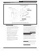
• The Direct Vent Conversion Kit described in
Appendix A is often required to avoid burner
“resonance” (a low-pitched humming noise)
when the boiler is installed at altitude. If the
Direct Vent Conversion Kit is required to
eliminate this noise, combustion air may still
be drawn from indoors if desired – see Figure
B.2).
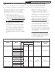
Table B.1 lists the specific differences
between the sea level and high altitude
configurations. Boilers that are factory
configured for use at altitudes above 2000ft
are marked as such on both the packaging
and rating plate. The high altitude orifice and
pressure switch are factory installed. The
appropriate Direct Vent Conversion Kit shown
in Table 2.2 is shipped in the boiler crate.
If indoor air is used for combustion - The
installer may elect to not install the Direct Vent
Conversion Kit unless burner resonance is
observed. If the Direct Vent Conversion Kit is
used, install it according to the instructions
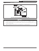
provided with the kit. After verifying that
there is an adequate air supply inside the
boiler room (see Section 5), install the intake
terminal directly on the boiler’s intake collar as
shown in Figure B.2. Secure with at least two
sheet metal screws.
If combustion air is drawn from outside
– Install the Direct Vent Conversion Kit
according to the instructions provided with
the kit. Then install the air intake system in
accordance with Appendix A.
Table B.1 Sea Level vs High Altitude Configurations
Elevation Model
Main Burner Orifice
Direct Vent Kit
Air Pressure
Switch
Qty
Drill Size (PN)
Nat. Gas LP
Sea Level - 2000 ft
PVCG30CN or P 4
#48
(822726)
#56
(822707)
Optional
109839-01
(1.24 Max Break)
PVCG40CN or P 6
PVCG50CN or P 8
PVCG60CN or P 10
PVCG70CN or P 12
PVCG80CN or P 14
2001-10,200 ft
PVCG30CN or P 4
#49
(822709)
#57
(822706)
Standard
Equipment
110096-01
(0.85 Max Break)
PVCG40CN or P 6
PVCG50CN or P 8
PVCG60CN or P 10
PVCG70CN or P 12
PVCG80CN or P 14