
Install Instructions


7
109837-01 - 5/20
PVCG-C
Installation, Operating & Service Manual
4 Locating the Boiler
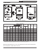
A. Clearances:
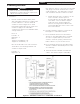
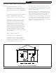
• Provide clearance between boiler jacket
and combustible material in accordance with
local fire ordinances. Observe minimum
clearances shown in Figure 4.1 to avoid
potential fire hazard. Except as noted, these
clearances apply to all combustible
construction as well as noncombustible walls,
ceilings and doors.
Front - 4”
Left Side - 4”
Right Side - 1”
Rear - 1”
Top (Closet installation) - 18”
Top (Alcove installation) - 4"
Note: As an alternate to the side clearances
shown above, the following minimum side
clearances may be used:
Left Side – 1”
Right Side – 4”
WARNING
Failure to observe the following location
requirements could result in a fire, explosion or
carbon monoxide (CO) hazard.
!
Note that if this option is exercised, the relief valve
and gauge must still be installed in the location
shown in Figure 4.1. The drain valve on the left
side of the boiler must also remain accessible.
• Provide practical service clearances. A 24”
service clearance from the jacket is
recommended on the left, right, and front
of the boiler. These clearances may be
reduced to those shown in Figure 4.1,
however servicing the boiler will become
increasingly difficult as these service clear-
ances are reduced.
B. Provide a minimum clearance of 1/2" from hot
water pipes to combustible material.
C. Do not install this boiler in a location where
gasoline or other flammable vapors or liquids,
or sources of hydrocarbons (i.e. bleaches,
cleaners, chemicals, sprays, paint removers,
fabric softeners, etc.) are used or stored.
D. Do not install this boiler in an area where large
amounts of airborne dust will be present, such
as a workshop.
E. The boiler must be installed on a hard level
surface. This surface may be combustible.
Figure 4.1: Minimum Clearances To Combustible Construction