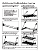
Pro Series 2x4ft Wall Mounted Shelf Warning: Excessive weight hazard! Use two or more people to move, assemble, or install Wall Mounted Shelf to avoid back or other injury. Do not leave children unattended near Wall Mounted Shelf, High risk of items falling if Wall Mounted Shelf is installed incorrectly: must be securely installed to avoid serious injury. For assistance, call 1.877.306.8930; e-mail at counterproductive.
[INDEX Product Overview: Safety Warning 3 Tools Needed 5 Included Quantities 6 Spare Parts -7 Weight Capacity 8 Installation Overview 8 Installation Overview: Installation Options 10 Wall Configuration: Installation Location 11 Ceiling Configuration: Installation Location 12 Installing Wall Brackets & Back Bean 13,14 Wall Configuration: Installing Pad Eye Plate 15 Perimeter Beam & Cable Assembly-16 Ceiling Configuration: Installing Pad Eye Plate 17 Perimeter Beam & Cable Assembly 18 Cable Assembly 19 Cross
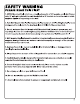
'SAFETY WARNING ) PLEASE READ THIS FIRST 1. All Wall Mounted Shelf units have a rated load capacity of 600 pounds, evenly distributed, using 3" lag bolts anchored into solid wood studs or 3" concrete anchors into solid concrete supports capable of supporting such a load. 2. Each Wall Mounted Sheaf utility hook can hold a maximum of dibs. Weight of utility hook storage must be included in the maximum load of 600ibs for the overhead rack. 3. Do not load more than 600Ibs onto a Wall Mounted Shelf.
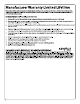
Manufacturer Warranty Limited Lifetime When this product is installed, operated and maintained according to the Instructions attached to or furnished with the product, Ne Wage Products inc. will replace the defective product or parts if the part falls as a result of defective materials or workmanship for the Lifetime of the product. SEWAGE PRODUCTS INC. WILL NOT PAY FOR: Service calls to correct the Installation of any Ne Wage products or to instruct you how to use or install them. 2.
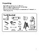
Unpacking « Begin by placing the package on a covered flat surface. « Remove all cardboard, packaging material and clear plastic bags. « Dispose / recycle all packaging materials. « Verify all the contents in the box and gather the required tools. See “Tools Needed”, and “Included Quantities” list.
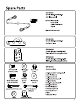
Spare Parts SKU 40481 Part § : Cable Assembly = 2ft Cable Assembly 4mm cable Aluminum Sleeve Capek = Quick Link Connector $KU 40482 Part & : Pad Eye Plates SKU 40484 Part # : Black Back Hanging Brackets SKU apps Part # : Whit Aback Hanging Brackets = ) 8 Carriage Bolt Flat Washer Acorn Nut (1/4” dia x 3/47) (1747 Hex Bolt rock Nut {5/16" dia x 1.25%) Flat Washer (/4" dial 0.75%) {1/47) @E Lag Screw (1/4” dia x 3%} Concrete Anchor {M6x 37 G L Pulley Pusey Cable Cap SKU 40483 Hardware Box x 0.
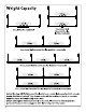
Weight Capacity Single Wall Mounted Shelf 4501bs. 3001bs Two Linked Wall Mounted Shelves Installed Vertically 450 bs. Two Linked Wall Mounted Shelves Installed Horizontally 400 ihs. 400 ibe.
Wall Mounted Shelf Installation Overview Determine your preferred configuration before beginning assembly. (Page 10) Plan your Wall Mounted Shelf installation location, determine orientation and verify spacing of studs. {Page 11-12) = Wall brackets must be fully secured to studs using 1 lag bolt each or to concrete wall using 1 concrete anchor. + Read through the entire instruction manual first before beginning Installation. Install wall brackets & back perimeter hems onto the wall at a determined height.
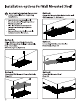
Installation options for Wall Mounted Shelf Important information: Please read Option A. entire manual before beginning Single Wall Mounted Shelf attached to wall. installation. (Start on page 11, Option A} < Layouts shown are examples only. = Do not exceed total weight capacity of Wall Mounted Shelf. + Plan layout and measure space for clearance and stud spacing before installing. = Ensure wall mounted shelf is securely installed to suitable structure. Option B.
Plan the Installation Location Option A: Installing Wall Mounted Shelf To the Wall Once it is determined that your Wall Mounted Shelf will be installed to the wall, verify there is sufficient clearance. Mark the desired position of the bottom of the Wall Mounted Shelf with a horizontal level line across the wall. Note: & Wall mounted configurations require greater than 26" between the ceiling and the bottom of the Wall Mounted Shelf.
Plan Installation Location Option B: Installing Wall Mounted Shelf To the Ceiling Once it is determined that your Wall Mounted Shelf will be installed to the ceiling, verify there is sufficient clearance. Mark the desired position of the bottom of the Wall Mounted Shelf with a horizontal level line across the wall. Note: e Ceiling mounted configurations can range from 18-33” {Adjustable in 1” increments) # The center of the Pad Eye plates mounted to the selling should be 22°from the back wall.
Installing Wall Brackets & Back Beam Align the bottom of the Wall Mounting Drill a pilot hole using a 3/16” drill bit. Bracket (#12) with the bottom level line Note: Pilot hole must bore into 3 inches and the center of the wall stud with of solid wood for lag screw to be fully the center of the horizontal slot in the secured.
Mark next location for pilot hole using the wall mounting bracket (#12) and rear perimeter beam Follow steps i through iii below. insert the Wall Mounting Bracket and Carriage Brit onto the Rear Perimeter Beam. Mount the Rear Perimeter Beam onto the previously installed Wall Mounting Bracket. @ Align the bracket with the level line drawn from step 2. Mark the wall location to be drilled along the center of the stud (as shown above).
Installing Pad Eye Plate Option A: Wall Configuration g: Measure and mark 26" vertically from the bottom of the Wall Mounted bracket {#12) to the top of the pad eye plate (#22) . Align the pad eye plate on the center of the stud and the top of the eye plate below the level line and mark the wall for pilot holes. Side View Wall Mounted: 26" @ Drill pilot holes into the solid wood using a 3/16” drill bit. Warning: Must bore info 3 inches of solid wood for lag screw to be fully secured.
Perimeter Beam & Cable Assembly Option A: Wall Configuration @ Attach cable eyelet to side beam using 5/16” bolt (#19) , nut (#20) and fender washer (#21) Wall Mounted Cable Assembly: Insert a 5/16" Hex Bolt into the 33rd hole of the side perimeter beam. @ insert a 5/16” Hex Bolt (#19) into the Front/First hole of the side perimeter beams.
Installing Pad Eye Plate Option B: Ceiling Configuration g @ {#12) and center of the ceiling joist, this will be the closest eye plate hole (#22) to the wall. Align the pad eye plate on the center of the ceiling joist and mark the ceiling for pilot holes.
Perimeter Beam & Cable Assembly Option B: Ceiling Configuration @ Attach cable eyelet to side beam using 5/16" bolt nut (#20) and fender washer (#21) Ceiling Mounted Cable Assembly: Attach the Cable Eyelet {#16) to the respective hole according to the distance measured from the ceiling 1o the bottom of the Wall Mounted Shelf. Example shown 18" from ceiling = 18th hole, insert a 5/16” Hex Bolt {#19) into the Front/First hole of the side perimeter beams.
Attach the Quick Link Connector (#1686} to the Pad Eye Plate Attach Side Beam{ #1/23) by guiding the mounting holes into the carriage bolt (#13) and shoulder rivet on the wall bracket.
Guide the mounting holes of the front beam (#4) into the shoulder rivets on the side perimeter beam. Use a rubber mallet to seat the rivets with the top of the keyholes.
2ft Cross Support Assembly {i} Assemble the 2§t Crass Supports (#5) with one 1/4” hex bolt (#5) and 1/47 lock nut {attache the assembled 28 cross supports to the perimeter frame with four hex bolts eight washers and four lock nuts (#7) Grid Supports & Wire Grids Installation {i} Begin at the side ends of the Wall Mounted Shelves and slide the 2t Finishing Grid Section with bent edges (#9) .
Moving inward, place remaining bottom “U” Shaped Grid Supports and Grid Sections onto the Wall Sheaf, L Wall Mounted Ceiling Mounted Warning: Periodically (at least quarterly) inspect your Wall Mounted Shelf unit to ensure brackets are seated properly and bolts are firmly connected to the studs/joists. if the Wall Mounted Sheaf has begun unseating, uninstall the Wall Mounted Shelf and install proper ceiling/wall support.
Installation Tips Installing with irregular Joist Spacing Pad eye plates can be positioned up to 6 inches side to side or 12 inches front to back to align with o ceiling joist. If you are not installing the pad eye plates in the intended location, the height of the shelf needs to be adjusted according to the values in the table below. SIDE VIEW § . FRONT VIEW Determine the distance of your pad eye plate from the intended original ceiling location (4) and hole position {B).
if the spacing of your ceiling joists do not match the desired size and direction of your Wall Mounted Shelf installation you will need to Install a jolts in the correct position. Please consult your local professional contractor for assistance installing a joist hanger. Using suitable joist hangers, install two additional wooden ceiling joists in the desired location.
if the spacing of your wall studs do not match 0 the desired size and direction of your Wall Mounted Shelf installation, you will need to install a horizontal! support brace in the correct position {minimum 2°x 8.
Connecting Wall Mounted Shelves Horizontally Install first wall shelf according to Note: Before installing the Wall option A (Wall Mounted) or B (Ceiling Mounting Brackets, ensure wall Mounted), until reaching Step 12 on mourned bracket will be shared page 16 or page 18. between two shelves that both carriage bolts are mounted where there will be insert a 5/16" Hex Bolt into the Front/First hole of the side perimeter beams.
Connecting Wall Mounted Shelf Vertically o Fully install upper wall shelf according Once you have followed steps 1 to 8 for the to option A (Wall Mounted) or B lower wall shelf, install the pad eye plates on {Ceiling Mounted]). Start installing your upper wall shelf according to diagram lower wall shelf up until Step 8 on below. You may need to remove the end Page.
Connecting Corner Wall Mounted Shelf Note: If installing two 2ftx8ft and one 2ftx4ft Wall Mounted Shelves in an L configuration, follow instructions starting on 18 of this page: Begin installing the 2fodft Wall Mounted Shelf by following the instructions below.
Attach the Rear Perimeter Beam followed by the Side Perimeter Beam, Bolt together the 2ftxdft Wall Mounted Shelf Front Perimeter Beam with the Side Perimeter Beam of the next Wall Mounted Shelf using one hex bolt and lock nut. Attach the Cable Assembly through both Perimeter Beams. Proceed and complete the assembly of the second Wall Mounted Sheaf beginning on step 3 {pg.13) of the Installation Manual.