
Installation Sheet
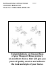

NWP-930B
Recommended Installation by a Professional Plumbing Contractor
Note: The use of petroleum base plumbers putty on our products will nullify the warranty. We recommend
the use of clear silicone sealing materials. Recommended deck hole Ø1.25.
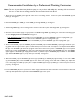
1. Place the pop-up GUIDE (1) through the center hole of mounting surface. Secure into place with WASHER (2) and
NUT (3). See Figure 1.
2. Assemble KNOB (4) to ROD (5). Insert ROD (5) through GUIDE (1). See Figure 1.
3. Install bridge BODY (6) onto mounting surface. Secure both sides in place with flange NUT (7). See Figure 2.
4. Connect hot/cold water supply to appropriate 1/2” NPSM bridge BODY (6), utilizing one of the three following types
of risers. Supply risers not included. See Figure 3.
a. 1/2” IPS flexible riser:
discard rubber nosecone WASHER (11), friction WASHER (12) and coupling NUT (13).
b. 3/8” or 1/2” OD bullnose riser:
utilize friction WASHER (12) and coupling NUT (13).
c. 1/2” copper riser: utilize rubber nosecone WASHER (11), friction WASHER (12) and coupling NUT (13).
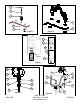
5. Remove drain PLUG (17) from FLANGE (18). Place FLANGE (18) and white WASHER (19) through sink drain open-
ing. (Clear silicone may be used in place of white washer.) From bottom side of sink, place cone shaped rubber WASH-
ER (20) onto FLANGE (18) and slide up against sink bottom. Note: Cone portion of WASHER (20) to face upward.
Next slide on white flat WASHER (21) and secure with flange NUT (22). Place white WASHER (23) into drain BODY
(24) & tighten to FLANGE (18). Apply thread sealant or plumbers tape to TAILPIECE (25) and attach to drain BODY
(24). Attach TAILPIECE (25) to p-trap drain (not included). See Figure 4.
6. Place drain PLUG (17) into FLANGE (18). Secure pop-up ROD (5) to STRAP (27), approximately 1" from end of ROD
(5), with SCREW (28). Insert ball ROD (29) into the drain's rod opening, secure with ball rod NUT (30). Adjust the
rise of the plunger and CLIP (31) into place. Adjust ball ROD (29) and pop-up ROD (5) so drain will open and close
properly. See Figure 5.
7. Remove AERATOR (32) from spout, turn on water supply, and flush both valves until water is clear. Check for leaks and
make any final adjustments required. Re-attach AERATOR (32) to the spout.