
Installation Sheet


NWP-1600
Recommended Installation by a Professional Plumbing Contractor
Note:The use of petroleum base plumbers putty on our products will nullify the warranty. We recommend the use of
clear silicone sealing materials. Recommended deck thru hole Ø 1.38"
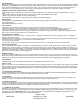
1. Insert HOSES (3), one at a time, and MOUNTING STUD (4) through ESCUTCHEON (2) and sink hole, (apply putty
or silicone to underside of ESCUTCHEON (2).Align SPOUT (1) and secure into place with mounting BRACKET (6)
and NUT (5). See Figure 1.
2. Place flange NUT (1) and fiber WASHER (2) onto valve BODY (3). Insert valve BODY (3) through sink hole from
underside of sink.Valve BODY (3) should extend 2-1/4” above mounting surface. If necessary adjust lower flange NUT
(1). Place fiber WASHER (2a) and flange NUT (1a) onto upper position of valve BODY (3). Set valve BODIES (3,3A)
so that their outlets are facing towards the center of the sink and tighten upper flange NUT (1a). See Figure 2.
3. Connect HOSE (4) to outlet of each valve BODY (3). Hand tighten and secure each HOSE (4) with a wrench 1/4
turn. See Figure 2.
4. Connect hot/cold water supply to appropriate 1/2” NPSM valve BODY (6), utilizing one of the three following types
of risers. Supply risers not included. See Figure 3.
a. 1/2” IPS flexible riser
: discard rubber nosecone WASHER (12), friction WASHER (13) and coupling NUT (14).
b. 3/8” or 1/2” OD bullnose riser: utilize friction WASHER (13) and coupling NUT (14).
c. 1/2” copper riser
: utilize rubber nosecone WASHER (12), friction WASHER (13) and coupling NUT (14).
5. Attach ESCUTCHEON (14), BONNET (15) and HANDLE (16). Any adjustments for rotational alignment must be
made to the valve body - not to the cartridge. (Note: Allow minimum spacing between HANDLE (16) and BON-
NET (15) to prevent damage to the surface finish.) Secure HANDLE (16) into place with setscrews. See Figure 4.
6. Remove drain PLUG (17) from FLANGE (18). Place FLANGE (18) and white WASHER (19) through sink drain
opening. (Clear silicone may be used in place of white washer.) From bottom side of sink, place cone shaped rubber
WASHER (20) onto FLANGE (18) and slide up against sink bottom. Note: Cone portion of WASHER (20) to face
upward. Next slide on clear flat WASHER (21) and secure with flange NUT (22). Place clear WASHER (23) into
drain BODY (24) & tighten to FLANGE (18). Apply thread sealant to TAILPIECE (25) and attach to drain BODY
(24). Attach TAILPIECE (25) to p-trap drain (not included). See Figure 5.
7. Place drain PLUG (17) into FLANGE (18). Insert pop-up ROD (26) through spout and secure to STRAP (27), approx-
imately 1" from end of ROD (26), with SCREW (28). Insert ball ROD (29) into the drain's rod opening, secure with
ball rod NUT (30). Adjust the rise of the plunger and CLIP (31) into place. Adjust ball ROD (29) and pop-up ROD
(26) so drain will open and close properly. See Figure 6.
8. Remove AERATOR (32) from spout, turn on water supply, and flush both valves until water is clear. Check for leaks
and make any final adjustments required. Re-attach AERATOR (32) to the spout.