
Installation Guide

NWP-1640
Recommended Installation by a Professional Plumbing Contractor
Note:The use of petroleum base plumbers putty on our products will nullify the warranty.We recommend
the use of clear silicone sealing materials. Recommended deck thru hole Ø 1.25"
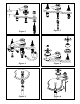
1. Place the spout shank through center hole of mounting surface. Secure spout, (spout base ring, if sup-
plied), into place with spout washer and nut. See Fig. 1
2. Place nut & washer on valve body. Insert body, (blue cold & red hot), through hole in the mounting sur-
face. Adjust and secure with additional washer and nut so that the top of valve is 2-1/16" above the top
of mounting surface. See Fig. 1
3. Place nylon washer into top of 4-way tee. Slide 4-way tee with nylon washer up against bottom of the
spout shank. See Fig. 2
4. Insert rubber washer, then brass washer, onto threaded nipple and into base opening of 4-way tee.
Secure with nut. See Fig. 2
5. Connect a flexible hose to side outlet of each valve body.Attach other end of hoses to either side of
the tee. (Hand-tighten and secure each connection with a wrench ¼ turn.) See Fig. 3
6. Attach hot/cold water supply hoses (not included) to appropriate valve, utilizing cone washers, friction
rings and nuts supplied. See Fig. 3
7. Attach escutcheon/bonnet and handles.Any adjustments for rotational alignment must be made to the
valve body - not to the cartridge. (Note: Allow minimum spacing between handles and escutcheon/bon-
net to prevent damage to the surface finish.) Secure handles into place with setscrew. See Fig. 4
8. Remove drain plug from flange. Place flange & white washer through sink drain opening. (Clear silicone
may be used in place of white washer.) From bottom side of sink, place cone shaped rubber washer
onto flange & slide up against sink bottom. Note: Cone portion of washer to face upward. Next slide on
clear flat washer and secure with flange nut. Place clear washer into drain body & tighten to flange.
Apply thread sealant to tailpiece and attach to drain body.Attach tailpiece to p-trap drain (not included).
See Fig. 5
9. Place drain plug into flange. Insert pop-up rod through spout and secure to strap, approximately 1" from
end of rod, with screw.
Insert ball rod into the drain's rod opening, secure with ball rod nut Adjust the rise of the plunger and
clip into place. Adjust ball rod and pop-up rod so drain will open and close properly. See Fig. 6
10. Remove aerator from spout, turn on water supply, and flush both valves until water is clear. Check
for leaks and make any final adjustments required. Re-attach aerator to the spout.