
Installation & Assemebly
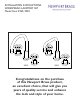

NWP-2920 Rev A
Recommended Installation by a Professional Plumbing Contractor
Note: The use of petroleum base plumbers putty on our products will nullify the warranty. We recommend
the use of clear silicone sealing materials.
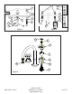
Recommended deck thru hole Ø 1.38"
1. Place the spout’s threaded ROD (1) and HOSES (2) through center hole of mounting surface. Secure
spout into place with rubber GASKET (3), mounting CRESCENT (4) and NUT (5). See Figure 1.
2. Place NUT (7) and WASHER (8) on valve BODY (6). Insert BODY (6), (blue cold & red hot), through
hole in the mounting surface. Adjust and secure with additional WASHER (8) and NUT (7) so that the
top of valve is 2” above the top of mounting surface. See Figure 1.
3. Connect HOSES (2) to side outlet of each valve BODY (6). Hand-tighten and secure each connection
with a wrench ¼ turn. See Figure 2.
5. Connect hot/cold water supply to appropriate 1/2” NPSM valve BODY (6), utilizing one of the three fol-
lowing types of risers. Supply risers not included. See Figure 2.
a. 1/2” IPS flexible riser:
discard rubber nosecone WASHER (9), friction WASHER (10) and coupling NUT
(11).
b. 3/8” or 1/2” OD bullnose riser: utilize friction WASHER (10) and coupling NUT (11).
c. 1/2” copper riser:
utilize rubber nosecone WASHER (9), friction WASHER (10) and coupling NUT (11).
5. Insert O-RING (16) to underside of ESCUTCHEON (12). Place ESCUTCHEON (12) and BONNET (13)
onto cartridge. Place HANDLE (14) over cartridge stem. Any adjustments for rotational alignment must
be made to the valve BODY (6) – not to the cartridge. (Note: Allow minimum spacing between HANDLE
(14) and BONNET (13) to prevent damage to the surface finish.) Secure HANDLE (14) into place with
SCREW (15). Then insert CAP (17) onto HANDLE (14). See Figure 3.
6. Remove AERATOR (18) from spout, turn on water supply and flush both valves until water is clear.
Check for leaks and make any final adjustments required. Re-attach AERATOR (18) to the spout.
See Figure 3.