
Installation Sheet

B
efore you begin
Make sure valve is securely fastened to studs. Be sure to remove trim items, handles, escutcheons and plates before
installation. Wrap carefully and store until finished wall is completed.
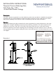
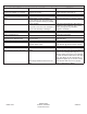
Install the valve by positioning the 1/2” shower outlet in the up position. Finished wall must be within dimensions
shown on the chart below.
On tiled wall surfaces, grouting must be either flush or raised for proper sealing of the cover plate.
IMPORTANT
: It is not necessary to remove the cartridge from the valve during
NORMAL
soldering operations using
propane-butane gas.
DO NOT USE OXYGEN-ACETYLENE
. When soldering CxC connections, do not solder within
4” of valve port. Open the stop valves when soldering inlets.
To test pipe joints, pressurize both hot and cold inlets.
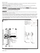
Installing Trim
Place cover plate on valve stem and slide into position. Install escutcheon/bonnet trim and mark the all-thread nipple,
(Item 1) were excess needs to be trimmed.
Remove escutcheon/bonnet trim and cut all-thread nipple 1/16” less than indicated mark to prevent exposure of nipple
threads. NOTE: Do not cut stem, (Item 6), or all-thread nipple until finished wall is complete and a dimension check of
handle and escutcheons/bonnet trim is done. (Stem is grooved at ½” intervals) Cut stem at least ½” past the end of
the cut all-thread nipple. Final stem length may vary based on individual handle base insertion. Reinstall escutcheon/bon-
net trim and handle. Secure handle into place by tightening the handle setscrew. (Ref. Illustrations 2 & 3) Turn on water
supply to check for leaks.
Illustration 2
Face of stud
Escutcheon
All thread
nipple
Broach stem
4” hole for valve
Cover plate
Handle
Retaining plate
Stop block
Locking nut
Face of finished wall
NOTE: Dimensions shown are from the inlet ports to the finished wall.
NWP-1-594
Face of stud
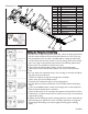
Ensure that the stop ring (3) is
c
orrectly installed as follows:
Rotate the cartridge stem (13)
fully clockwise.
Position the stop ring on the
stem such that it rests against
the stop post (14).
The stop ring must be correctly
installed prior to finish trim
installation.
31/8”
33/4”
1-3/8”Min