
Installation Sheet

NWP-1-587 11/29/2017
EN-3222
Rev A
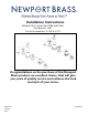
Rough In Valve Installation
Recommended Installation by a Professional Plumbing Contractor
Note: Use plumbers tape or equivalent to seal all threaded joints. Plumb with 3/4” copper
pipe is recommended.
Warning: To prevent severe damage to valve body, any solder/braze process must be
performed a min. of 4" from ports.
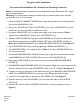
1. Install the QUICK CONNECT FLANGE (3) through appropriate hole of mounting surface.
Secure with WASHER NUT (1A).
2. Place lower WASHER NUT (1B) on VALVE BODY (12). Insert VALVE BODY (12), (blue
cold & red hot), through hole from underside of deck.
3. Use upper WASHER NUT (1C) to adjust stem height from finished deck per Table 1.
Tighten lower WASHER NUT (1B) to secure VALVE BODY (12).
4. Remove UPPER FLANGE NUT (4) and install DIVERTER VALVE (10) from underside of
deck. Reattach and bottom out UPPER FLANGE NUT (4) onto DIVERTER VALVE (10).
Note: place UPPER FLANGE NUT (4) on FINISHED DECK SURFACE (2). See Figure 1a.
5. Secure DIVERTER VALVE (10) to deck by tightening LOWER FLANGE NUT (11).
6. Trim DIVERTER STEM (13) to height shown in Table 1. Cut ALL THREAD NIPPLE (14)
1/2” shorter than stem
7. Install HAND SHOWER DECK FLANGE (5) housing through hole on finished deck surface,
install RUBBER (6) and STEEL WASHER (7) and secure with FLANGE NUT (8).
8. Place plastic HOSE GUIDE (9) onto lower portion of housing HAND SHOWER DECK
FLANGE (5).
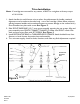
9. Feed BRAIDED HAND SHOWER HOSE (15) through deck flange and connect female thread
hose into the hand shower outlet of DIVERTER VALVE (10) 1/2”-14 NPSM. See Figure 2.
10. Use tape or string to temporary tie the male thread end of the BRAIDED HAND SHOWER
HOSE (15) to DIVERTER STEM (13) to prevent it from falling underneath the deck.
11. Attach hot/cold supply lines to appropriate VALVE BODY (12). See Figure 2.
12. Connect outlet from each VALVE BODY (12) to the two side inlets of the DIVERTER
VALVE (10).
13. Connect 3/4” bottom outlet of DIVERTER VALVE (10) to tub spout fitting as shown in
Figure 2.