
Installation Guide


Trim Installation
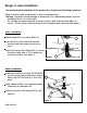
Utilizing 3/4” copper pipe, make connections between spout, valves and water supply.
See Figure 3.
Warning:
To prevent severe damage to valve body, any solder/braze process must be per-
formed a min. of 4" from ports.
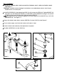
Install ESCUTCHEON (9), place broached ROD (11) with o-ring onto STEM (20). Tighten BONNET (10)
over ROD (11) and onto ESCUTCHEON (9). Install LEVER (7) over BONNET (10). Align & secure with
SCREW (8). Press end CAP (12) with o-ring into top of LEVER (7).
NNoottee
: Any adjustments for rotational alignment must be made to the valve BODY (2), not to the
CARTRIDGE (20). See Figure 4.
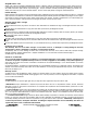
Using a thin blade screw driver, remove AERATOR (11) from SPOUT (4). See Figure 5.
Turn on water supply, and flush both valves until water is clear.
Check for leaks and make any final adjustments required.
Re-attach AERATOR (11) to the SPOUT (4).
Figure 3
Inlet for
hot water
supply
Inlet for
cold water
supply
Figure 4
Figure 5
9
8
7
11
4
10
11
20
12