
Installation

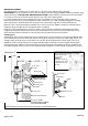
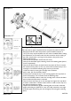
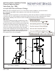
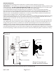
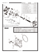

Table Of Contents

NWP-1-595
BEFORE YOU BEGIN
On tiled wall surfaces, grouting must be either flush or raised for proper sealing of the cover plate.
IMPORTANT: It is not necessary to remove the cartridge from the valve during NORMAL soldering operations using
propane-butane gas. DO NOT USE OXYGEN-ACETYLENE. When soldering connections, do not solder within
4” of valve port. Do not use excessive heat. Open the stop valves when soldering inlets.
It is recommended that the pipes be flushed clean prior to installation, in order to avoid any future problems.
Ensure that the stop ring is properly installed, see below, otherwise a user could potentially disengage the cartridge
with minimal force to external handle. This would cause the valve to fail, losing control of flow & temperature.
Make sure valve is securely fastened to studs. Be sure to remove trim items, handles, escutcheons and plates before
installation. Wrap carefully and store until finished wall is completed.
Install the valve by positioning the 1/2” shower outlet in the up position. If installing showerhead & hand shower
configuration, plumb showerhead from tub port (T) and hand shower from shower port (S). Finished wall must be
within dimensions shown in illustration 2. To test pipe joints, pressurize both hot and cold inlets.
Installing Trim
Thread plastic upper link into finished post. Insert assembled post onto end of diverter stem, then slide finished sleeve
over attached items and screw sleeve into diverter housing. Place coverplate on valve stem while sliding diverter trim
through rubber grommet. Screw on escutcheon trim and mark all-thread nipple where excess needs to be cut off.
(NOTE: For stem to be fully seated into cartridge, all-thread nipple and locking nut must be tightly secured against
retaining plate.) Place handle on stem. Measure excess between escutcheon and handle base. Remove handle and cut
previously measured excess from end of stem. Reinstall handle and tighten set screws. (Refer to Illustrations 2 and 3.)
Illustration 2
Escutcheon
All thread nipple
Broach stem
4-1/2” hole
for valve
Cover plate
Handle
Retaining plate
Stop block
Locking nut
NOTE: Dimensions shown are from the inlet ports to the finished wall.
Grommet
Diverter knob
Diverter stem
Face of Finished Wall
Ensure that the stop ring (3) is correctly installed,
prior to finished trim installation, as follows:
- Rotate the cartridge
stem (13) fully
clockwise.
- Position the stop ring
on the stem such that it
rests against the stop
post (14).
06/23/20
3-1/8”
3-3/4”
1-1/4"
3-1/4” to 3-7/8"
Installed position against
Face of Finished Wall