
Installation Sheet


IIIa. Installing Trim & Temperature Setting for the following series: 3-2404TR, 3-
2414TR, 3-2484TR, 3-2524TS, 3-2534TS, 3-2544TS, 3-2554TR, 3-2044TS
1. Remove and discard mud cover and screws.
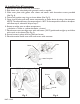
2. Slide Sleeve over Valve body with grooved notch to topside.
3. Slide Thermo Wall Plate with o-rings over Sleeve and attach with screws (See Fig 4a).
4. Slide Thermo over wall Plate , flush on finished wall and oriented with 100° mark at the top
(See Fig 5a).
5. Position limit Stop Ring with orientation shown below (See Fig 5a).
6. Open shut-off valve and verify water temperature at outlet device by using a thermometer.
Note: The safe and factory set temperature is 100°F. If the temperature needs to be adjust-
ed: Rotate Cartridge Stem to adjust temperature: (clockwise=colder or counterclock-
wise=hotter).
7. Place Bonnet onto cartridge stem with red button (100°F) positioned
straight up and inline with notch on the Sleeve(See Fig 6a).
8. Secure Bonnet in place with set screw (See Fig 6a)
Stop Ring
Cartridge
Stem
Fig. 5a
Fig. 6a
Bonnet
Fig. 4a
Valve
Sleeve
Thermo Cover Plate
Thermo Wall Plate
Optional Extension Kit
2-260 available
NWP-1-540