
Installation

I. Rough in Valve Installation
Note: Use plumbers tape or equivalent to seal all threaded port joints. This valve is designed to
fit in a 2" X 4" stud wall (or thicker) installation. Use stem extension kit #2-260 (sold seperately)
if valve installed is too far away from the finished wall.
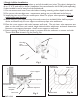
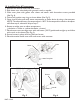
1. Do not remove mud cover from valve before locating mounting surface depth in the wall.
2. Do not turn the cartridge stem - temperature settings are pre-calibrated at the factory.
3. Install plug into one of the two outlet ports. Note: For proper valve operation only one
outlet port may be used.
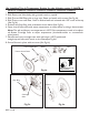
4. Mount valve to cross support using shims and screws (not included). Valve shall be perpen-
dicular and fixed firmly to cross support to achieve proper trim attachment.
5. Place the cross support with valve between wall studs. The min./max. valve exposure tem-
plate on the mud cover and vertical height desired within tub/shower enclosure determines
the exact cross support placement. Attach cross support to wall studs.
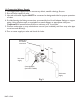
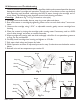
6. Ensure opening in finished wall comes in contact with the mudcover to ensure seal with
Thermo Wall Plate shown in Fig. 4a. (See Fig 2a).
Plug
Shim
Fig. 1
Cartridge
stem
DO NOT TURN
Maximum exposure
Minimum exposure
Finished wall
Mud cover
Mud cover
template
Wall stud
Cross support
Fig. 2
NWP-1-540
Finished Wall
Opening in
Finished Wall
Mud Cover
Fig. 2a