
Installation & Assembly

Recommended Installation by a Professional Plumbing Contractor
Note: The use of petroleum base plumbers putty on our products will nullify the warranty. We
recommend the use of clear silicone sealing materials.
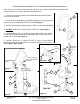
1. Drill hole in mounting surface. Recommended deck hole Ø1.350”
not to exceed Ø1.562”.
2. Insert Hoses through base O-RING (1) and hole in mounting surface.
Secure into place with MOUNTING KIT (3). See Figure 1.
3. Attach hot/cold water supply directly to valves in the wall. See Fig. 2
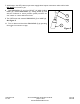
4. DO NOT remove the HOSE (6) from SPOUT (4). See Figure 3.
5. Attach WEIGHT (8) to HOSE (6) in the appropriate area shown,
on the upward swing toward the SPRAYHEAD (5), in order to provide
proper pull to hose. See Figure 4.
6. Connect HOSE (6) to valve OUTLET (7). Note: The two tabs of
HOSE (6) fitting must properly line up with the opening of OUTLET (7)
See Figures 4A and 4B.
1
3
5
4
Mounting
Surface
Hole
9/16-24 UNEF (FOR
3/8” COMPRESSION
OUTLET)
3/8” COMPRESSION
OUTLET
4
6
8
7
5
6
7
6
Figure 1
Figure 2
Figure 3
Figure 4A
Figure 4
6
Figure 4B
7
Tabs
Outlet
Openings
NWP-8200-5103
2001 CARNEGIE AVE, SANTA ANA CA 92705 02/01/18
Rev NC (949) 417-5207 EN-3528
WWW.NEWPORTBRASS.COM