Decking Installation Guide v20151224
IMPORTANT: Read all sections before you start For the most up to date information please visit our website @ www.newtechwood.com Prior to installing any composite decking it is recommended that you check with local building codes for any special requirements or restrictions. The diagrams and instructions outlined in this guide are for illustration purposes only and are not meant or implied to replace a licensed professional.
Heat and Fire Excessive heat on the surface of NewTechWood products from external sources such as but not limited to fire or reflection of sunlight from energy efficient window products. Low-emissivity (Low-E) glass can potentially harm NewTechWood products. Low-E glass is designed to prevent passive heat gain within a structure and can cause unusual heat build-up on exterior surfaces.
Fasteners Continued Sealant Always use screws designated for use with composite decking material. Always test the screws on a scrap piece of board to ensure the screws do not cause the surface of the decking to mushroom or bulge around the head of the screw. If it does cause this issue, change to a different brand of screw.
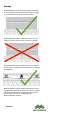
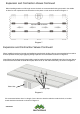
Storage NewTechWood’s products always need to be stored on flat solid surfaces. Surfaces such as dirt and grass are not sufficient as they can move over time. NewTechWood products shown above put on a flat surface on joists, this is the correct way for storage. NewTechWood products shown above on an uneven surface which will make the products prone to warping and distortion. NewTechWood products shown shown above can be on pedestals or jacks if the surface is uneven.
Framing First, determine the decking span, that is , how far apart your joists will be. The frame needs to be completely level before installing any boards. Note: Adequate spacing in the joists is required to keep the deck boards from bending. Please review the chart on page 9 of this installation guide to see what spacing is required for your profile.
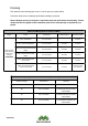
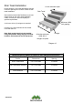
Expansion and Contraction Values NewTechWood deck boards will experience expansion and contraction with changes in temperature. Expansion and contraction are most significant where extreme temperature changes occur. Fastening the deck planks according to the gapping requirements noted in the following table accommodates for this movement. Length (Feet) 3.3 8.0 9.2 9.8 12 12.8 13.1 16 17.
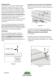
Expansion and Contraction Values Continued When installing boards one full length across the deck we recommended locking the board in the middle to allow for even expansion and contraction to take place on both ends as shown in Diagram 7.
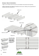
Breaker Board Installation Diagram 9 and 10 below show how framework and installation of the breaker board respectively. Diagram 9 framework uses a ladder joist installation where the user is building a frame perpendicular for the board that will be running down it. Ladder Joist Diagram 9 Breaker Board T Clip Ladder Joist Diagram 10 Note: The T-Clip can be used as a breaker board clip by cutting it in half as shown in Diagram 11.
Stair Tread Installation Review Diagram 12 and the table below with the maximum spacing from center to center for stair tread installation. 11 inch minimum depth Stair Tread Stair treads built with NewTechWood must meet requirements by the major national building codes. Consult your local municipality for specific requirements. Minimum 13/64 inch gapping A minimum of four (4) stringers are required. Overhang on a stair tread should not exceed more than 5/8 inch.
Bullnose Installation Use the table on the previous page to determine the center to center spacing for the bullnose profile. Bullnose Installation: 1. Now take the bullnose profile and place it right over all the TC-5 starting clips and push down as show in Diagram 14. A minimum of four (4) stringers are required when installing the bullnose profile. Overhang on a stair tread should not exceed more than 5/8inch. Starting Accessory Installation: 1.
Bullnose Installation Continued: 3. Now take the next board and have it situated behind the bullnose profile as shown in Diagram16. Diagram 16 4. Slide in the clips into the two grooves and glide them along until they are on their respective joists and then screwing down onto the joists as shown in Diagram 17 and 18. Diagram 18 5. Finally, finish your last board by face fixing into the board at every joist as shown in Diagram 19. Note: Remember to pre-drill before face fixing into the board.
Bullnose Installation Continued Diagram 20 below shows a completed staircase from the side to get a better idea of how the final installation will look.
Framing First, determine the decking span, that is , how far apart your joists will be. Starting Accessory Installation Continued: 3. Then take your first board and push it into the starting accessory as shown in Diagram 22. The frame needs to be completely level before installing any boards. Note: Adequate spacing in the joists is required to keep the deck boards from bending. Please review the chart on page 5 of this installation guide to see what spacing is required for your profile.
T Clip and Locking Clip Installation Continued: 2. After getting all the TC-1 and TC-2 clips into position above each respective joist, begin to fasten them from above as shown in Diagram 24 and 25. 3. The final installed clips should look like Diagram 26. Locking Clip T Clip Diagram 26 Diagram 24 Diagram 25 Note: The fastest way of installation is by pushing all the boards together and then coming back and sliding the clips into the grooves from the side and then fixing from above.
Option 2: UltraLock System 1. First slide the UL-1 and UL-2 clips into the grooves of the boards at a 30-45 degree angle at their respective joists as shown in Diagram 27. 3. Next, screw the clips into the joists using a 45 degree angle Diagram 27 Diagram 29 2. Once the clip is in press down and the clip will be ready to install into the joists as shown in Diagram 27 & 28. Diagram 28 Note: Using hidden fasteners that are not manufactured by NewTechWood nor recommended by NewTechWood are not warranted.
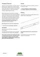
Option 2: UltraLock System Continued: 5. Repeat steps 1-4 until the deck is complete. 6. The final installed clips should look like Diagram 31. UL-1 UL-2 Diagram 31 Note: The locking clip is in the middle of Diagram 31 to show the expansion and contraction is happening in both directions. For more information on how to install the locking clips and their placement check page 9 of this installation guide.
Fascia Board Installation Installing against the width and length of decking 1. The fascia should be installed on the rim board of the frame. The fascia should be installed as shown in Diagram 32. The distance between screws must be less than or equal to 12 inches. Two screws must be used 1” 1/2 away from the ends 300 mm hes c 12 in Diagram 32 2. First pre-drill the holes for the fascia board.
End Cap Installation Installing the end cap 1. Place the end cap infront of the hollow boards holes (UH02 or UH07) and push in as shown in Diagram 33. Note: A mallet could be used as well to push in the end caps. Silicon Diagram 33 2. The final finish should look like Diagram 34 below. Note: A dab of silicon (shown in Diagram 33) can be used on the end cap or inside the holes of the board in order to secure the end caps better.
Installation Guide v20151224 NewTechWood Ltd. 19111 Walden Forest Dr. Suite B Humble, TX 77346, USA Toll Free in USA: 1-866-728-5273 Tel: (+1) 281-570-6450 Fax: (+1) 281-661-1167 Email: inquiry@newtechwood.com Web: www.newtechwood.