NexLink NL102PLUS User Manual NEXAS www.nexastech.com V1.
NexLink NL102PLUS User Manual Disclaimer All information, illustrations, and specifications contained in this manual are based on the latest information available at the time of publication. The right is reserved to make change at any time without notice.
NexLink NL102PLUS User Manual TABLE of CONTENTS 1. INTRODUCTION .................................................................................. 1 2. GENERAL INFORMATION .................................................................. 1 2.1 ON-BOARD DIAGNOSTICS (OBD) II ..................................................... 1 2.2 DIAGNOSTIC TROUBLE CODES (DTCS)................................................ 2 2.2.1 OBDII DTC ..............................................................................
NexLink NL102PLUS User Manual 1. INTRODUCTION The NL102P is specially developed for car, SUV, mini Van, Light duty and heavy duty vehicles, which supports all 10 modes of OBDII test (EVAP, O2 Sensor, I/M Readiness, MIL Status, VIN Info, and On-board monitors testing etc.) for a complete diagnosis and enables users to read DTCs, clear DTCs and view the datastream with a live color graphing. It covers a wide range of vehicles since it offers multiple data bus protocols, such as J1587 and J1939.
NexLink NL102PLUS User Manual 2.2 Diagnostic Trouble Codes (DTCs) Diagnostic Trouble Codes (DTC) are codes that are stored by the on-board computer diagnostic system in response to a problem found in the vehicle. These codes identify a particular problem area and are intended to provide you with a guide as to where a fault might be occurring within a vehicle. 2.2.1 OBDII DTC OBD II Diagnostic Trouble Codes consist of a five-digit alphanumeric code.
NexLink NL102PLUS User Manual 2.2.2 DTCs for J1587/J1708 and J1939 This section explains the basic elements of fault codes for J1587/J1708 and J1939 data bus protocols, how to view these codes on NL102P, and what they mean. Each fault code on NL102P contain three distinct pieces of information, as described below. J1587/J1708 fault codes consist of the following, in this order: Subsystem Identifier (SID) – Indicates what function on the ECU has failed.
NexLink NL102PLUS User Manual SAE J1708 makes up the physical and data link layers while SAE J1587 makes up the transport and application layers with respect to the OSI model. SAE J1587 is used in conjunction with SAE J1708 for automobile communication. SAE J1939 SAE J1939 is the vehicle bus standard used for communication and diagnostics among vehicle components, originally by the car and heavy duty truck industry in the United States.
NexLink NL102PLUS User Manual repairs are completed or the condition no longer exists. DTC -- Diagnostic Trouble Codes (DTC) that identifies which section of the emission control system has malfunctioned. Enabling Criteria -- Also termed Enabling Conditions. They are the vehicle-specific events or conditions that must occur within the engine before the various monitors will set, or run. Some monitors require the vehicle to follow a prescribed “drive cycle” routine as part of the enabling criteria.
NexLink NL102PLUS User Manual exhaust heat in normal operation or by adding a catalyst to the filter) or actively introducing very high heat into the exhaust system. 2.6 Service Reset Service Reset – It is performed some sensor calibration or reset After replace or clean some sensors like O2 sensor, EGR Delta Pressure Sensor, ATD Maximum Sensor, etc. 3. Product Descriptions 3.1 Outline Figure 3-1 No. Name Descriptions ① OBD II Cable Connects the NL102P to the vehicle’s Data Link Connector (DLC).
NexLink NL102PLUS User Manual ③ ESC button Returns to previous menu. ⑤/⑧ / button Move cursor up or down for selection. ④/⑨ / button Move cursor right or left for selection; Or turn page up or down when more than one page is displayed. ⑥ USB port Connects to computer to update online. ⑩ OK button Confirms a selection (or action) from menu list. ⑦ ? button Help of live data and DTC 3.2 Specifications Screen: 2.
NexLink NL102PLUS User Manual vehicle’s on-board computer and usually located in the driver’s cab. A plastic DLC cover may be found for some vehicles and you need to remove it before plugging the 6 pin or 9 pin DLC diagnostic adaptor. If it cannot be found, refer to the vehicle’s service manual for the location. 2. Plug one end of 6 pin or 9 pin DLC diagnostic adaptor into the included OBD II 16 pin connector, and connect the other end to the heavy duty vehicle’s DLC. 3.
NexLink NL102PLUS User Manual 4. Connections & General Operations 4.1 Connections 1. Turn the ignition off. 2. Locate the heavy duty vehicle’s DLC. 3. Select the desired diagnostic adaptor according to your vehicle’s DLC. 4. Plug one end of 6pin or 9pin DLC diagnostic adaptor into the included OBD II 16 pin connector, and connect the other end to the heavy duty truck’s DLC. 5. Turn the ignition on. Engine can be off or running. 6.
NexLink NL102PLUS User Manual CAUTION: Don’t connect or disconnect any test equipment with ignition on or engine running. 4.2 HD DPF The HD DPF function perform the DPF reset or regeneration. From Main Screen (Figure 4.1), use the [ ] / [ ] scroll button and [ ] / [ ] scroll button to select vechile make and press the [OK] button to start. 4.3 HD Service The HD Service function perform the sensor reset or calibration. From Main Screen (Figure 4.
NexLink NL102PLUS User Manual 3) Unit system setting: Set the measurement unit system. 5. Diagnose In Figure 4-1, press [OK] to scan the protocols of heavy-duty trucks and OBDII vehicles, a screen similar to figure 5-1 will appear: Figure 5-1 If a vehicle equipped with OBDII is tested, the system will enter the function selection screen once scanning has finished successfully. Figure 5-2 Press [OK] to enter the system selection screen. For detailed operations, please refer to Chapter 5.
NexLink NL102PLUS User Manual figure 5-3. Figure 5-3 For detailed operations, please refer to Chapter 5.1 “HD OBD Diagnosing”.
NexLink NL102PLUS User Manual Select “HD OBD” Select communication protocol Select test system Read DTC (Refer to Chapter 5.1.1) Select test function Clear DTC (Refer to Chapter 5.1.2) View All Items Live Data (Refer to Chapter 5.1.3) Select Items View Graphic Items Figure 5-5 5.
NexLink NL102PLUS User Manual Figure 5-6 5.1.1 Read DTC This option is used to read the current activated or historical activated trouble codes. Generally, there are three elements for one J1939 DTC (See Figure 5-7): Suspect Parameter Number (SPN) – Indicates what function on the ECU has failed. Failure Mode Indicator (FMI) – Indicates in what way the function failed. Occurence (OC) – Indicates the occurence times of the current DTC.
NexLink NL102PLUS User Manual Press [ ] / [ ] to view the next or previous trouble code; press [ESC] to exit and return to the function screen. 5.1.2 Clear DTC This option allows you to clear the existing or historic trouble codes. Note: After clearing, you should retrieve trouble codes once more or turn ignition on and retrieve codes again. If there are still some trouble codes in the system, please troubleshoot the code using a factory diagnosis guide, then clear the code and recheck. 5.1.
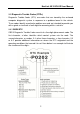
NexLink NL102PLUS User Manual Figure 5-9 5.2.1 Read Codes This option is used to read the current, pending or permanent trouble codes. If the trouble code is found, the system will display the detailed description of the trouble code: Figure 5-10 Figure 5-11 In Figure 5-10, 3/12 indicates there are total 12 codes and P0102 is the third code to display. If the DTC is defined by the manufacturer, a screen similar to Figure 5-11 will appear.
NexLink NL102PLUS User Manual 5.2.2 Erase Codes It is used to clear all existing trouble codes. Notes: Before performing this function, make sure to retrieve and record the trouble codes. After clearing, you should retrieve trouble codes once more or turn ignition on and retrieve codes again. If there are still some trouble codes in the system, please troubleshoot the code using a factory diagnosis guide, then clear the code and recheck. 5.2.
NexLink NL102PLUS User Manual depending on vehicle. 5.2.6 O2 sensor test The results of O2 sensor test are not live values but instead the results of the ECU’s last O2 sensor test. For live O2 sensor readings, refer to any of the live sensor screens such as Graph Screen. Not all test values are applicable to all vehicles. Therefore, the list generated will vary depending on vehicle. In addition, not all vehicles support the Oxygen Sensors screen. 5.2.
NexLink NL102PLUS User Manual Support: Engine Make Function DOC Cleaning Procedures MAXXFORCE DPF Regeneration DPF Onboard DPF Regeneration In Parking DETROIT COMMINS DPF Regeneration In Driving Aftertreatment Diesel Particulate Filter Regeneration ISUZU DPF Regeneration HINO DPF Regeneration More To Update DPF Regeneration Note: All SHEETs illustrated here are for reference and demonstration purpose only and REAL FUNCTION is up to the product.
NexLink NL102PLUS User Manual More To Update ………….. Note: All SHEETs illustrated here are for reference and demonstration purpose only and REAL FUNCTION is up to the product. This User’s Manual is subject to change without prior notice. 8. FAQ Here we list some frequently asked questions and answers relating to NL102P. Question: System halts when reading data stream. What is the reason? Answer: It may be caused by a slackened connector.
NexLink NL102PLUS User Manual NEXAS TECH CO.,LTD www.nexastech.com V1.