
User Manual


14
FORM NO. L-20205-C-1209
4
2
9
5
6
25
21
16
20
15
3
12
14
13
8
24
14
13
12
7
19
18
1
11
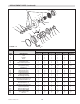
FIGURE 14
17
QUANTITY
ITEM DESCRIPTION 5H30PSP-E 5H35PSP-E 5H40PSP-E 5H45PSP-E 5H50PSP-E 5H60PSP-E
1 Hub 1 1 1 1 1 1
2 Cylinder 1 1 1 1 1 1
3 Piston 1 1 1 1 1 1
4 Rotary Seal 1 1 1 1 1 1
5 Anti-Rotation Clip 1 1 1 1 1 1
6 Button Head Cap Screw 2 2 2 2 2 2
7 Backing Plate 1 1 1 1 1 1
8
1
Compression Spring 6 10 12 13 15 18
11
1
Ball Bearing 1 1 1 1 1 1
12
1
Ball Bearing 3 3 3 3 3 3
13 Retaining Ring (Int.) 2 2 2 2 2 2
14 Retaining Ring (Ext.) 2 2 2 2 2 2
15
1
O-Ring Seal (Large) 1 1 1 1 1 1
16
1
O-Ring Seal (Small) 1 1 1 1 1 1
17 Drive Flange Assembly 1 1 1 1 1 1
Socket Head Cap Screw (Included in 17) 3 3 3 3 3 3
Drive Flange (Included in 17) 1 1 1 1 1 1
Enclosure (Included in 17) 1 1 1 1 1 1
Drive Ring (Included in 17) 1 1 1 1 1 1
Balls (Included in 17) 5 5 5 5 5 5
Ball Carrier (Included in 17) 1 1 1 1 1 1
18 Set Screw (190-24) 2 2 2 2 2 2
19 Set Screw (250-20) 4 4 4 4 4 4
20
1
Back-Up Ring (Large) 1 1 1 1 1 1
21
1
Back-Up Ring (Small) 1 1 1 1 1 1
24 Spring Stiffener Pin 6 10 12 13 15 18
25 Air Line 1 1 1 1 1 1
1
Denotes Repair Kit Item.
REPLACEMENT PARTS (continued)