GEO S12 Series Geo S1210 & Geo S1230 Tangent Array Modules LS18 & LS18e Subwoofer User Manual GEO S12 Series User Manual V1.
Page 2/103 PLEASE READ CAREFULLY BEFORE PROCEEDING GEO Technology is radically new thinking The GEO R&D Project has, to date, resulted in the following patent applications: The GEO Hyperboloid Reflective Wavesource™ differs radically from the megaphonevariant type horns you know and love (or hate). “Tried and true” methods will produce entirely unexpected results. HRW technology produces precise and predictable results. The Configurable Directivity Flange.
PLEASE READ CAREFULLY BEFORE PROCEEDING Page 3/103 PLEASE READ CAREFULLY BEFORE PROCEEDING BASIC PRECAUTIONS Do not open the speaker system or attempt to disassemble the internal parts or modify them in any way. The speaker system contains no user-serviceable parts. If it should appear to be malfunctioning or damaged, discontinue use immediately and have it inspected by qualified NEXO service personnel.
Page 4/103 PLEASE READ CAREFULLY BEFORE PROCEEDING SAFETY INSTRUCTIONS FOR NEXO TD CONTROLLERS NEXO ANALOGUE PSTDCONTROLLERS, NX242 DIGITAL CONTROLLER, NXAMP4x1 AND NXAMP4x4 POWERED CONTROLLERS ARE CLASS 1 APPARATUS AND MUST BE EARTHED. THE GREEN AND YELLOW WIRE OF THE MAINS CORD MUST ALWAYS BE CONNECTED TO AN INSTALLATION SAFETY EARTH OR GROUND. THE EARTH IS ESSENTIAL FOR PERSONAL SAFETY AS WELL AS THE CORRECT OPERATION OF THE SYSTEM, AND IS INTERNALLY CONNECTED TO ALL EXPOSED METAL SURFACES.
PLEASE READ CAREFULLY BEFORE PROCEEDING Page 5/103 HIGH SOUND PRESSURE LEVELS Exposure to extremely high noise levels may cause permanent hearing loss. Individuals vary considerably in susceptibility to noise-induced hearing loss but nearly everyone will lose some hearing if exposed to sufficiently intense noise for a sufficient period of time. The U.S.
Page 6/103 CONTENTS CONTENTS PLEASE READ CAREFULLY BEFORE PROCEEDING ..................................................................................................................... 3 CONTENTS ................................................................................................................................................................................................ 6 1 INTRODUCTION .....................................................................................................
CONTENTS Page 7/103 8.4.4 Single GEO S12 flown horizontally .......................................................................................................................................... 49 8.4.5 Two GEO S12 on wind-up stand ............................................................................................................................................... 50 8.4.6 Two GEO S12 flown horizontally..........................................................................................
Page 8/103 1 INTRODUCTION INTRODUCTION Thank you for selecting a NEXO GEO S12 Series Tangent Array System. This manual is intended to provide you with necessary and useful information about your GEO S12 System, which includes the following products: GEO S1230 is a 30° Tangent Array Module. It comprises 1x12” (30cm) Neodynium 16 ohms LF/MF driver and 1x3” voice coil, 1.4” Throat 16 Ohm HF Driver loaded by a 28.5° Hyperboloid Reflective Wavesource™. GEO S1210 is a 10° Tangent Array Module.
INTRODUCTION Page 9/103 GEO S12 Accessory Range. a full range of accessories that provides safe, flexible and simple means of installing Geo S12 Tangent Arrays in fixed installation as well as in touring applications. As for all NEXO systems, GEO S12s are controlled, powered and monitored by dedicated NEXO TDControllers: NXAMP4x1 and NXAMP 4x4 are Powered Digital Controllers, providing full control and amplification for RS15 in multiple configurations.
Page 10/103 INTRODUCTION NS-1 simulation software assists in the design and implementation of vertical tangent GEO arrays. Please consult the NEXO web site (www.NEXO.fr or www.NEXO-sa.com) for the latest software releases. Please devote your time and attention to reading this manual. A comprehensive understanding of GEO theory, tangent arrays and specific features of GEO S12 and LS18 will help you to operate your system at its full potential.
GEO S12 GENERAL SET-UP INSTRUCTIONS 2 Page 11/103 GEO S12 GENERAL SET-UP INSTRUCTIONS 2.1 Speaker connection GEO S12 and LS18 is connected with Speakon NL4FC plugs (not supplied). A wiring diagram is printed on the connection panel located on the back of each cabinet. The 4 pins of the 2 Speakon sockets identified in / out are connected in parallel within the enclosure.
Page 12/103 2.1.4 GEO S12 GENERAL SET-UP INSTRUCTIONS Cabling NEXO recommends the exclusive use of multi-conductor cables to connect the system: the cable kit is compatible with all the cabinets, and there is no possible confusion between LF, MF and HF sections. Cable choice consists mainly of selecting cables of the correct sectional dimension (size) in relation to the load resistance and the cable length.
GEO S12 GENERAL SET-UP INSTRUCTIONS Page 13/103 C A A B C B D D CONNECTOR PANEL PASSIVE MODE ACTIVE MODE
Page 14/103 3 AMPLIFIER SELECTION FOR USE WITH GEO S12 & LS18 AMPLIFIER SELECTION FOR USE WITH GEO S12 & LS18 3.1 GEO S12, LS18 and NXAMP TDControllers NEXO Powered TDControllers NXAMP 4X1 & 4X4 are integrated solutions for Control and amplification for all NEXO speaker ranges.
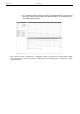
GEO S12 SETUPS ON NEXO TD CONTROLLERS 4 4.1 Page 15/103 GEO S12 SETUPS ON NEXO TD CONTROLLERS NXAMP TDControllers As of today, load 3.15 features the setups listed in below table in the “Nexo configurations” menu. Keep in mind that the “custom configuration menu” allows to build any combination of NEXO speakers with - full phase compatibility from 20 Hz to 20kHz. - Choice between 85 Hz and 120 Hz X-over point between LS18 and Geo S12. Please consult www.nexo-sa.com for upgrade releases.
Page 16/103 5 5.
CONNECTION DIAGRAMS 5.
Page 18/103 5.
CONNECTION DIAGRAMS 5.
Page 20/103 5.
CONNECTION DIAGRAMS 5.
Page 22/103 5.
CONNECTION DIAGRAMS 5.
Page 24/103 6 NS-1 SIMULATION SOFTWARE NS-1 SIMULATION SOFTWARE NS-1 software is a R&D simulation tool derived application. It processes measured speaker data with complex mathematical algorithms to assist the user in optimizing system design. Due to the complexity of the interaction of multiple cabinets, it is simply not possible to reliably design curved vertical arrays without using the processing power of a computer to predict the optimum array structure for a given audience geometry.
CONFIGURABLE DIRECTIVITY DEVICE 7 Page 25/103 CONFIGURABLE DIRECTIVITY DEVICE The GEO Wavesource controls dispersion of acoustic energy using an hyperboloid acoustical reflector in the “coupling plane” (the vertical plane of a curved vertical tangent array) and a diffraction slot in the “non-coupling plane” (the horizontal plane of a curved vertical tangent array). The patented Configurable Directivity Device consists of bolt-on flanges that alter the diffraction slot’s exit flare rate. 7.
Page 26/103 7.2 CONFIGURABLE DIRECTIVITY DEVICE When & where to use Configurable Directivity flanges The diagrams show audience area coverage for a stereo system. While the GEO cluster will deliver even SPL from the front to the rear of this audience area, there are “holes” near the front in the centre and at the outside edges. We cannot fill the outside coverage gaps without enlarging the centre gap, and vice versa (left figure below).
GEO S12 HARDWARE SETUP PROCEDURE 8 Page 27/103 GEO S12 HARDWARE SETUP PROCEDURE Before proceeding with assembly of GEO S12 & LS18 arrays, please ensure that the components are present and undamaged. A component list is appended to this manual. In the event of any shortage, please contact your supplier. For maximum efficiency the GEO S12 & LS18 rigging system requires three experienced persons for set-up: typically one motor hoist operator, and one operator per side of the array.
Page 28/103 8.1.2 GEO S12 HARDWARE SETUP PROCEDURE When deploying a GEO S12 & LS18 system always wear protective headwear, footwear and eye protection. Do not allow inexperienced persons to handle a GEO S12 & LS18 system. Installation personnel should be trained in loudspeaker flying techniques and should be fully conversant with this manual.
GEO S12 HARDWARE SETUP PROCEDURE 8.1.3 Page 29/103 Never allow anyone, whether operators, artists or members of the public to climb onto a ground stacked PA system. Anyone who needs to climb over 2m (6 ft) high should be fitted with suitable safely equipment including a clip-on harness. Please refer to local Health and Safety legislation in your territory. Your dealer can help with advice on access to this information. Apply the same attention to all safety matters when de-stacking systems.
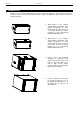
Page 30/103 8.2 GEO S12 HARDWARE SETUP PROCEDURE General Description GEO S1230 GEO S1210 GEO S1230, GEO S1210 and LS18 incorporate two connecting plates (one per side) on which a comprehensive range of accessories can be mounted.
GEO S12 HARDWARE SETUP PROCEDURE 8.2.1 Page 31/103 Described configurations SECTION 8.3.2 SECTION 8.3.2 SECTION 8.3.4 SECTION 8.3.3 SECTION 8.3.5 SECTION 8.3.7 FIXED INSTALLATIONS SECTION 8.4.3 SECTION 8.4.9 SECTION 8.4.7 SECTION 8.4.2 SECTION 8.4.4 SECTION 8.4.5 TOURING APPLICATIONS SECTION 8.4.6 SECTION 8.4.
Page 32/103 8.2.2 GEO S12 HARDWARE SETUP PROCEDURE WARNINGS ON GEO S12 ACCESSORIES WARNING 1 All GEO S12 & LS18 Accessories are specifically rated in agreement with structural computations. Never use other accessories – including push-pins - when assembling GEO S12 & LS18 cabinets than the ones provided by NEXO: NEXO will decline responsibility over the entire GEO S12 & lS18 accessory range if any component is purchased from different supplier.
GEO S12 HARDWARE SETUP PROCEDURE 8.3 8.3.1 Page 33/103 GEO S12 in fixed installations Fixed installation Accessories and kits Accessories are: Bumper for Geo S12 & LS18 (VNI-BUMPER1) “U” Bracket (VNI-UBRK12) “L” Bracket for cable suspension (VNI-LBRK) “U” Bracket for rigid suspension (VNI-ABRK) Connecting Plates / range : 0.20° - 3.15° (VNI-ANPL1) Connecting Plates / range : 5.00° - 10.0° (VNI-ANPL2) Connecting Plates / range : 16.0° - 30.
Page 34/103 8.3.2 GEO S12 HARDWARE SETUP PROCEDURE Single GEO S12 rigidly mounted on a wall or a ceiling (vertical or horizontal) Required items 1 x GEOS12-UBRK (allows all angles to be implemented) 4 x 12mm diameter screws (not provided) IMPORTANT Ensure that the surface – wall or ceiling – is strong enough to hold GEO S12 weight and that the for screws 12mm diameter and corresponding plugs required to fix the “U” bracket on the wall or under the ceiling are properly dimensioned.
GEO S12 HARDWARE SETUP PROCEDURE 8.3.3 Page 35/103 Single GEO S12 cable mounted on a wall or a ceiling (vertical or horizontal) Required items 1 or 2 x VNI-LBRK (allows cable suspension, holes for cable suspension are 10mm diameter); 2 or 4 slings and corresponding shackles (not provided) IMPORTANT Ensure that the ceiling is strong enough to hold GEO S12 weight and that the cable suspension system required to install the cabinet under the ceiling is properly dimensioned.
Page 36/103 8.3.4 GEO S12 HARDWARE SETUP PROCEDURE GEO S12 vertical array rigidly mounted on a ceiling Required items 1 x VNI-BUMPER (allows +/-5° bumper tilt when installed below a flat surface; if higher bumper tilt is required, surface will have to be defined accordingly) ; (N-1) x VNI-ANPL for a N x GEO S12 array (ANPL1 ranges from 0.2° to 3.
GEO S12 HARDWARE SETUP PROCEDURE Page 37/103 (9) Apply Loctite 243 or equivalent to four shoulder screws from the last VNI-CPLA kit; (10) Position the VNI-BUMPER bumper to required angle position and use the four shoulder screws to connect it the bumper to the top cabinet; (11) Flip GEO S12 cluster by 90° so that it is ready to be positioned under the ceiling; (12) Four screws 12mm diameter (not provided) are required to secure the bumper under the ceiling.
Page 38/103 8.3.5 GEO S12 HARDWARE SETUP PROCEDURE LS18 & GEO S12 vertical array rigidly mounted on a ceiling Required items 1 x VNI-BUMPER (allows +/-5° bumper tilt when installed below a flat surface; if higher bumper tilt is required, surface will have to be defined accordingly) ; (M-1) x VNI-ANPL1 for M x LS18 M x LSI-CPLA counter-plates for M x LS18 N x VNI-ANPL for a N x GEO S12 (ANPL1 ranges from 0.2° to 3.
GEO S12 HARDWARE SETUP PROCEDURE Page 39/103 (5) Apply Loctite 243 or equivalent to the screws that attach the LS18 connector plate to the cabinet, and reinstall the LS18 connector plates (see figure below left); (6) Position Geo S12 bottom counter-plates (see figure below left); (7) Position VNI-ANPL1 angle plates (set at 0.
Page 40/103 GEO S12 HARDWARE SETUP PROCEDURE (11) Flip cluster by 90° so that it is ready to be positioned under the ceiling; (12) Four screws 12mm diameter (not provided) are required to secure the bumper under the ceiling.
GEO S12 HARDWARE SETUP PROCEDURE 8.3.6 Page 41/103 LS18 and GEO S12 vertical array cable mounted on a ceiling Required items As in 2 sections above, plus 2 x VNI-LBRK (allows cable suspension for bumper, holes for cable suspension are 10mm diameter); 4 slings and shackles (not provided) IMPORTANT Ensure that the ceiling is strong enough to hold LS18 & GEO S12 cluster weight and that the cables suspension system required fixing the bumper under the ceiling is properly dimensioned.
Page 42/103 8.3.7 GEO S12 HARDWARE SETUP PROCEDURE GEO S12 horizontal array rigidly mounted on a ceiling Required items 2 x VNI-ABRK (allows rigid ceiling suspension for horizontal arrays) (N-1) x VNI-ANPL for a N x GEO S12 array (ANPL1 ranges from 0.2° to 3.
GEO S12 HARDWARE SETUP PROCEDURE Page 43/103 (7) Flip the cluster upside down to access connector plates located on the down side; (8) Repeat all above steps from #2 to #6; (9) Position the two “U” brackets from VNI-ABRK kits on the outer cabinets next the angle plates, and tight them to the cabinets using the shoulder screws provided with these kits (using Loctite 243 or equivalent); (10) Four screws 12mm diameter (not provided) are required to secure the “U” brackets under the ceiling;
Page 44/103 8.3.8 GEO S12 HARDWARE SETUP PROCEDURE GEO S12 horizontal array cable mounted on a ceiling Required items 2 x VNI-LBRK (allows cable suspension for horizontal arrays, holes for cable suspension are 10mm diameter); (N-1) x VNI-ANPL for a N x GEO S12 array (ANPL1 ranges from 0.2° to 3.15°, ANPL2 ranges from 5° to 10°, ANPL3 ranges from 16° to 30°); N x VNI-CPLA for N x GEO S12 array; 4 slings and 4 shackles (not provided).
GEO S12 HARDWARE SETUP PROCEDURE 8.4 8.4.
Page 46/103 8.4.
GEO S12 HARDWARE SETUP PROCEDURE Page 47/103
Page 48/103 8.4.3 GEO S12 HARDWARE SETUP PROCEDURE Single GEO S12 flown vertically Required items 1 x Flying Bar for single vertical GEO S12 (VNT-TTC) 1 x Lifting Ring (VNT-XHBRK) Or 1 x Truss hook (VNT-TCBRK) IMPORTANT Ensure that truss suspension point is strong enough to hold GEO S12 weight.
GEO S12 HARDWARE SETUP PROCEDURE 8.4.4 Page 49/103 Single GEO S12 flown horizontally Required items 1 x “U” Bracket for single horizontal GEO S12 (GPT-SSBRK) 1 x Lifting Ring (VNT-XHBRK) Or 1 x Truss hook (VNT-TCBRK) IMPORTANT Ensure that suspension point is strong enough to hold GEO S12 weight.
Page 50/103 8.4.
GEO S12 HARDWARE SETUP PROCEDURE Page 51/103
Page 52/103 GEO S12 HARDWARE SETUP PROCEDURE Alternative Procedure (“Walder” procedure) Below described procedure required 2 additional 8x20 quick release pins (BLGEOS) Split the GPT-PSBRK side plates by removing screws and bolt; Slide GPT-PSBRK lower half-plates into lower GEO S12 connecting plate oblong holes; Lock safety pins into lower GEO S12 connecting plate; Position “U” bracket over these lower half plates; align centre holes; Insert adjustment handles, adjust vertical angle and
GEO S12 HARDWARE SETUP PROCEDURE Page 53/103
Page 54/103 8.4.6 GEO S12 HARDWARE SETUP PROCEDURE Two GEO S12 flown horizontally Required items 1 x “U” Bracket for two GEO S12s (GPT-PSBRK) 1 x Lifting Ring (VNT-XHBRK) Or 1 x Truss hook (VNT-TCBRK) IMPORTANT Ensure that suspension point is strong enough to hold two GEO S12s weight.
GEO S12 HARDWARE SETUP PROCEDURE 8.4.7 Page 55/103 Two or more GEO S12 flown vertically Required items N Pair of Rigging Plates (GPT-XBOW) for N cabinets; 1 lifting ring (VNT-XHBRK) every two GEO S12; 4xN Quick release pins for N cabinets; Properly rated slings, shackles, hoists… (not provided) IMPORTANT Lifting ring VNT-XHBRK and truss hook VNT-TCBRK are rated for a maximum of 2 GEO S12s; Ensure that suspension points are rated accordingly.
Page 56/103 GEO S12 HARDWARE SETUP PROCEDURE IMPORTANT GEO S12 can be flown “Up” or “Down”: - “Up” means Nexo logo on front grid is at the top; - “Down” means Nexo logo on front grid is at the bottom. GEO S12 can be connected “Up” or “Down” by simply flipping the cabinets.
GEO S12 HARDWARE SETUP PROCEDURE Page 57/103 Lift and position assembly, connect lifting rings to suspension points with sling and shackle; Secure assembly with secondary safety steel. IMPORTANT The requirements for secondary safety systems vary with territories. However, the secondary safety steel MUST have a SWL equivalent or greater than that of the rigging system.
Page 58/103 8.4.8 GEO S12 HARDWARE SETUP PROCEDURE LS18 and three or more GEO S12 flown horizontally Required items 1 x Bumper (GPT-BUMPER); M pairs of LS rigging plates (LST-XBOW) for M x LS18 cabinets; N Pair of Rigging Plates (GPT-XBOW) for Geo S12 cabinets; 4x(N+M) Quick release pins for (N+M) cabinets; 1 hoist (not provided). IMPORTANT Maximum GEO S12 quantity for flown vertical cluster is 12 (and eventually less).
GEO S12 HARDWARE SETUP PROCEDURE Page 59/103 Optional GPT-TLB link bar for GPT- XBOW GPT-XBOWs are delivered with standard link bars which allow both stacked and flown setups. However, these link bars require perfect alignment of angle setting holes when adding cabinets. GPT-XBOW STANDARD LINK BAR To facilitate flying operation, an optional link bar with oblong holes (GPT-TLB, pair of link bars provided with two 8x20 quick release pin) is available in the GEO S12 accessory range.
Page 60/103 GEO S12 HARDWARE SETUP PROCEDURE Procedure Insert LST-XBOW into connecting plates of both sides of LS18s; Insert GPT-XBOW into connecting plates of both sides of GEO S12s; Lock safety pins into LS18 and GEO S12s connecting plate IMPORTANT Ensure that safety pins are properly locked into LS18s and GEO S12s connecting panels.
GEO S12 HARDWARE SETUP PROCEDURE Page 61/103 IMPORTANT GEO S12 can be flown “Left” or “Right” : - “Left” means Nexo logo on front grid is left as seen from front; - “Right” means Nexo logo on front grid is right as seen from front. GEO S12 can be connected to bumper “Left” or “Right” by simply flipping the cabinets.
Page 62/103 GEO S12 HARDWARE SETUP PROCEDURE IMPORTANT Ensure angle settings are identical on both sides of the cabinets. Ensure that safety pins are properly locked into LS18s and GEO S12s connecting panels. Ensure that all quick release pins are properly locked into their position. Lift cluster to NS-1 defined rigging height, secure cluster horizontally to prevent it from rotating; Secure bumper with secondary safety steel.
GEO S12 HARDWARE SETUP PROCEDURE 8.4.
Page 64/103 GEO S12 HARDWARE SETUP PROCEDURE LS18 and GEO S12 ground stack device description GPT-GSTK ground stack device includes: two supporting beams, which support assembly weight; two connecting beam, which allow connection of the beams to the first cabinet; one reinforcement beam, to rigidify ground stack device sideways; Axis, “R” clips and handles to assemble the ground stack device Assemble the two connecting beam and the reinforcement beam with the handles; Depending on t
GEO S12 HARDWARE SETUP PROCEDURE Insert GPT-XBOW into connecting plates of both sides GEO S12s; Insert LST-XBOW into connecting plates of LS18s Lock safety pins into LS18s and GEO S12s connecting plate; Page 65/103 IMPORTANT Ensure that safety pins are properly locked into LS18s and GEO S12s connecting panels.
Page 66/103 GEO S12 HARDWARE SETUP PROCEDURE Connect bottom LS18 or GEO S12 to GPT-GSTK Ground stacking device with 4 8x20 quick release pins; Connect second LS18 or Geo S12 with X-Bow front articulation holes and rear link bars and ensure quick release pins are properly locked; Repeat above steps for subsequent cabinets
GEO S12 HARDWARE SETUP PROCEDURE Page 67/103 Once the assembly is completed, rotate rear or front GEO S12 ground stack device adjustable legs to definitive tilt angle, ensuring that +/-10° is never exceeded on bottom GEO S12.
Page 68/103 8.5 GEO S12 HARDWARE SETUP PROCEDURE Testing and Maintenance of the system General: Geo is a precision piece of equipment and requires regular attention to maintenance in order to give long and reliable service. NEXO recommends regular testing of loudspeaker rigging components, preferably using a suitable test rig coupled with a visual inspection. Fasteners: there are several critical points in the LS18GEO S12 cabinets.
SYSTEM ALIGNMENT GUIDELINES 9 Page 69/103 SYSTEM ALIGNMENT GUIDELINES The NX242’s factory delay presets are optimised to provide the best possible crossover between the GEO S12 and CD18 / S2 / GEO SUB systems. The reference point for this adjustment is the front of each cabinet. (This means that the internal delays needed to achieve a correct time alignment are set for cabinets standing next to each other with both fronts aligned).
Page 70/103 9.3 SYSTEM ALIGNMENT GUIDELINES Driving the LS18s from the AUX send It is quite common to use the AUX send of a mixing desk to drive the Sub section of a PA system. This gives the mixing engineer more flexibility to set the level of the subbass relative to the main PA, apply special effects, or to use a different EQ on the Sub. However, it also raises some serious issues for the performance & safety of the system (mostly time alignment).
SYSTEM ALIGNMENT GUIDELINES 9.4 Page 71/103 Recommended installation tools and equipment Tape measure – should be 30m/100ft in length and be of durable fibre material. Have one per array available to speed up the installation process. Laser Inclinometer – For measuring vertical and horizontal angles in the venue. An ideal product is the Calpac ‘Laser projecting a dot’ version which costs approximately 60 €.
GEO S12 – LS18S SYSTEM CHECK LIST Page 72/103 10 GEO S12 – LS18S SYSTEM CHECK LIST It is essential to execute all these check steps prior to perform a sound check on the “front end” to the system. Following this checklist step by step will prevent many troubles and will save time in the end. 10.1 Are the speakers properly connected and angled ? Attach the first series of modules to the bumper. Before flying, verify that all channels of all modules are functioning properly.
TECHNICAL SPECIFICATIONS Page 73/103 11 TECHNICAL SPECIFICATIONS 11.1 LS18 Subwoofer 11.1.
Page 74/103 11.1.
TECHNICAL SPECIFICATIONS Page 75/103 11.2 GEO S1230 Module 11.2.1 System specifications PRODUCT FEATURES GEO S1230 Shape HF: 1 x 3” voice coil, 1.4” throat 16 Ohms driver on a 5° hyperboloid reflective wavesource. LF: 1 x 12” (30cm) high excursion neodymium 16 Ohm driver. 344 x 675 x 400 mm (13 1/2” x 26 1/2” x 15 1/2”) excluding accessories 1/2 Rigging axis to axis height: 345mm (13 ”) 30° Trapezoid. Weight: net 26.8 kg (59.1 lbs) excluding accessories.
Page 76/103 11.2.2 Dimensions 11.2.
TECHNICAL SPECIFICATIONS Page 77/103 11.3 GEO S1210 Module 11.3.1 System specifications PRODUCT FEATURES GEO S1210 Shape HF: 1 x 3” voice coil, 1.4” throat 16 Ohms driver on a 5° hyperboloid reflective wavesource. LF: 1 x 12” (30cm) high excursion neodymium 16 Ohm driver. 344 x 675 x 378 mm (13 1/2” x 26 1/2” x 14 7/8”) excluding accessories 1/2 Rigging axis to axis height: 345mm (13 ”) 10° Trapezoid. Weight: net 28.05 kg (61.8 lbs) including array assembly system.
Page 78/103 11.3.2 Dimensions 11.3.
TECHNICAL SPECIFICATIONS 11.4 GEO S12 Touring Applications Accessories 11.4.1 GPT- BUMPER Parts Dimensions Weight 20 kg / 44.
Page 80/103 11.4.
TECHNICAL SPECIFICATIONS 11.4.3 GEO S12 Rigging Plates Parts Dimensions Weight (pair) 10.7 kg / 23.
Page 82/103 TECHNICAL SPECIFICATIONS 11.4.4 Tension Mode Link Bars for GPT-XBOW Parts Dimensions Weight (pair) 0.6 kg / 1.
TECHNICAL SPECIFICATIONS 11.4.5 Lifting Ring Parts Dimensions Weight (kit) 0.3 kg / 0.
Page 84/103 TECHNICAL SPECIFICATIONS 11.4.6 Truss hook for GPT-PSBRK or GPT-SSBRK Parts Dimensions Weight (kit) 0.620 kg / 1.
TECHNICAL SPECIFICATIONS 11.4.7 Truss hook for single vertical GEO S12 Parts Dimensions Weight (kit) 0.7 kg / 1.
Page 86/103 TECHNICAL SPECIFICATIONS 11.4.8 “U” Bracket for single vertical GEO S12 Parts Dimensions Weight (kit) 7 kg / 15.
TECHNICAL SPECIFICATIONS 11.4.9 U” Bracket for two vertical GEO S12 Parts Dimensions Weight (kit) 10.4 kg / 22.
Page 88/103 11.4.10 TECHNICAL SPECIFICATIONS Ground Stacking Device for up to 6 GEO S1210 Parts 04GPT-GSTK Dimensions Weight (kit) 26.5 kg / 58.
TECHNICAL SPECIFICATIONS 11.5 GEO S12 Fixed Installations Accessories 11.5.1 LS18 & GEO S12 Bumper (VNI-BUMPER) Parts Dimensions Weight (kit) 14.
Page 90/103 11.5.
TECHNICAL SPECIFICATIONS 11.5.
Page 92/103 TECHNICAL SPECIFICATIONS 11.5.4 LS18 & GEO S12 Connecting Plate 1 (VNI-ANPL1) Parts Dimensions Weight (kit) 7.5 kg / 16.
TECHNICAL SPECIFICATIONS 11.5.5 GEO S12 Connecting Plate 2 (VNI-ANPL2) Parts Dimensions Weight (kit) 6.2 kg / 13.
Page 94/103 TECHNICAL SPECIFICATIONS 11.5.6 GEO S12 Connecting Plate 3 (VNI-ANPL3) Parts Dimensions Weight (kit) 5.5 kg / 12.
TECHNICAL SPECIFICATIONS 11.5.7 Single GEO S12 “U” Bracket Parts Dimensions Weight 2.9 kg / 6.
Page 96/103 11.5.8 “L” Bracket for cable suspension Parts Dimensions Weight (kit) 1.75 kg / 3.
TECHNICAL SPECIFICATIONS 11.5.9 “U” Bracket for rigid suspension Parts Dimensions Weight (kit) 1.75 kg / 3.
Page 98/103 11.5.10 TECHNICAL SPECIFICATIONS GEO S12 Push-Pins (04VXT-BL820) 04VXT-BL820 WEIGHT: 0.032 KG / 0.
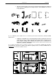
GEO S12 SERIES PARTS & ACCESSORIES LIST Page 99/103 12 GEO S12 SERIES PARTS & ACCESSORIES LIST 12.1 Modules & Control Electronics List MODEL DRAWING DESCRIPTION Subwoofer Module LS18 GEO S1230 GEO S1230 Module GEO S1210 GEO S1210 Module NXAMP4x1 Digital Powered Controller 4x1300W NXAMP4x4 Digital Powered Controller 4x4000W 12.2 Accessories List MODEL DRAWING DESCRIPTION GPT-BUMPER Main GEOS12 Bumper for touring application. LST-XBOW Rigging plates for LS18 touring applications (pair).
Page 100/103 GEO S12 SERIES PARTS & ACCESSORIES LIST MODEL DRAWING DESCRIPTION VNT-XHBRK Lifting Ring for GPT-SSBRK or GPT-PSBRK or GPTXBOW (includes 8x45 Quick Release Pin).
GEO S12 SERIES PARTS & ACCESSORIES LIST MODEL DRAWING Page 101/103 DESCRIPTION VNI- LBRK “L” Bracket for cable suspension (for fixed installation). VNI- ABRK “U” Bracket for rigid suspension (for fixed installation).
Page 102/103 13 USER NOTES USER NOTES
USER NOTES France Nexo S.A. Parc d’activité de la dame jeanne F-60128 PLAILLY Tel: +33 3 44 99 00 70 Fax: +33 3 44 99 00 30 E-mail: info@nexo.fr www.nexo-sa.