
Data Sheet


©
Nexperia B.V. 2017. All rights reserved
BZX585_SERIES All information provided in this document is subject to legal disclaimers.
Product data sheet Rev. 5 — 11 October 2016 3 of 13
Nexperia
BZX585 series
Voltage regulator diodes
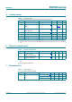
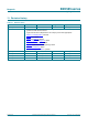
5. Limiting values
[1] t
p
=100s; square wave; T
j
=25C before surge
[2] Device mounted on an FR4 Printed-Circuit Board (PCB) with approximately 35 mm
2
Cu area at cathode
tab.
6. Thermal characteristics
[1] Device mounted on an FR4 Printed-Circuit Board (PCB) with approximately 35 mm
2
Cu area at cathode
tab.
[2] Soldering point of cathode tab.
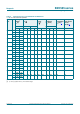
7. Characteristics
[1] Pulse test: t
p
300 s; 0.02.
Table 5. Limiting values
In accordance with the Absolute Maximum Rating System (IEC 60134).
Symbol Parameter Conditions Min Max Unit
I
F
forward current - 200 mA
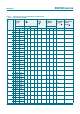
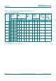
I
ZSM
non-repetitive peak reverse
current
[1]
-see
Table 8
and 9
P
ZSM
non-repetitive peak reverse
power dissipation
[1]
-40W
P
tot
total power dissipation T
amb
25 C
[2]
-300mW
T
amb
ambient temperature 65 +150 C
T
j
junction temperature 65 +150 C
T
stg
storage temperature 65 +150 C
Table 6. Thermal characteristics
Symbol Parameter Conditions Min Typ Max Unit
R
th(j-a)
thermal resistance from
junction to ambient
in free air
[1]
- - 350 K/W
R
th(j-sp)
thermal resistance from
junction to solder point
[2]
--65K/W
Table 7. Characteristics
T
j
=25
C unless otherwise specified.
Symbol Parameter Conditions Min Typ Max Unit
V
F
forward voltage
[1]
I
F
=10mA --0.9V
I
F
= 100 mA - - 1.1 V