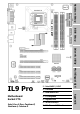
Hardware Setup BIOS Setup Driver & Utility Motherboard Socket 775 PCI Express FSB1066 Dual DDR2 667 Gigabit LAN 4x SATA 3Gb/s 7.
IL9 Pro User’s Manual English + Multilingual QIG 1st Edition, October 2006 Copyright and Warranty Notice The information in this document is subject to change without notice and does not represent a commitment on part of the vendor, who assumes no liability or responsibility for any errors that may appear in this manual. No warranty or representation, either expressed or implied, is made with respect to the quality, accuracy or fitness for any particular part of this document.
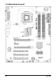
Hardware Setup Contents 1. Hardware Setup ............................................................... 1-1 1.1 1.2 1.3 1.4 1.5 1.7 1.9 Driver & Utility 1.8 BIOS Setup 1.6 Specifications ..............................................................................1-1 Motherboard Layout.....................................................................1-2 Choosing a Computer Chassis .......................................................1-3 Installing Motherboard ................................
iv IL9 Pro
Hardware Setup 1. Hardware Setup 1.1 Specifications • 3x PCI CPU • Support Intel Core 2 Duo, Pentium D, Pentium 4, Celeron D Processor with 1066MHz FSB • Supports Intel Hyper-Threading Technology Internal I/O Connectors • 1x Floppy port • 1x ATA 100 IDE connector • 4x SATA 3Gb/s connectors • 2x USB 2.
1.
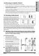
• Choose a chassis big enough to install this motherboard. • As some features for this motherboard are implemented by cabling connectors on the motherboard to indicators and switches or buttons on the chassis, make sure your chassis supports all the features required. • If there is possibility of adopting some more hard drives, make sure your chassis has sufficient power and space for them. • Most chassis have alternatives for I/O shield located at the rear panel.
1.5 Checking Jumper Settings • • For a 2-pin jumper, plug the jumper cap on both pins will make it CLOSE (SHORT). Remove the jumper cap, or plug it on either pin (reserved for future use) will leave it at OPEN position. SHORT OPEN OPEN Pin 1~2 SHORT Pin 2~3 SHORT For 3-pin jumper, pin 1~2 or pin 2~3 can be shorted by plugging the jumper cap in. 1.5.
An onboard battery saves the CMOS memory to keep the BIOS information stays on even after disconnected your system with power source. Nevertheless, this backup battery exhausts after some five years. Once the error message like “CMOS BATTERY HAS FAILED” or “CMOS checksum error” displays on monitor, this backup battery is no longer functional and has to be renewed. To renew the backup battery: 1. Power off the system and disconnect with AC power source. 2. Remove the exhausted battery. 3.
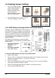
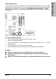
1.6 Connecting Chassis Components 1.6.1 ATX Power Connectors These connectors provide the connection from an ATX power supply. As the plugs from the power supply fit in only one orientation, find the correct one and push firmly down into these connectors. ATX 24-Pin Power Connector: The power supply with 20-pin or 24-pin cables can both be connected to this 24-pin connector. Connect from pin-1 for either type.
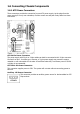
This header is used for connecting switches and LED indicators on the chassis front panel. Watch the power LED pin position and orientation. The mark “+” align to the pin in the figure below stands for positive polarity for the LED connection. Please pay attention when connecting these headers. A wrong orientation will only cause the LED not lighting, but a wrong connection of the switches could cause system malfunction.
1.6.3 FAN Power Connectors These connectors each provide power to the cooling fans installed in your system. • CPUFAN1: CPU Fan Power Connector • SYSFAN2~3: System Fan Power Connector ※ These fan connectors are not jumpers. DO NOT place jumper caps on these connectors. 1.6.4 Chassis Speaker Connector This header provides the connection to chassis speaker.
Hardware Setup 1.7 Installing Hardware ※ DO NOT scratch the motherboard when installing hardware. An accidentally scratch of a tiny surface-mount component may seriously damage the motherboard. ※ In order to protect the contact pins, please pay attention to these notices: 1. A maximum 20 cycles of CPU installation is recommended. 2. Never touch the contact pins with fingers or any object. 3. Always put on the cap when the CPU is not in use. 1.7.
5. Use your left hand to hold the load plate, and use your right thumb to peel the cap off. 8. Place the heatsink and fan assembly onto the socket. Align the four fasteners toward the four mounting holes on the motherboard. The cap plays an important role in protecting contact pins. In order to prevent bent pin, PUT ON the cap after operation or testing. 9. Press each of the four fasteners down into the mounting holes. Rotate the fastener clock-wise to lock the heatsink and fan assembly into position. 6.
Hardware Setup 1.7.2 DDR2 Memory Slots • To reach the optimum performance in dual-channel configurations, install identical DDR2 DIMM pairs for each channel. • Install DIMMs with the same CAS latency. To reach the optimum compatibility, obtain memory modules from the same vendor. ※ Usually there is no hardware or BIOS setup required after adding or removing memory modules, but you will have to clear the CMOS memory first if any memory module related problem occurs. To install system memory: 1.
1.7.3 PCI Express X16 Add-on Slots These slots support the connections of graphics cards that comply with PCI Express specifications. This motherboard provides dual PCI-Express X16 slots for one or two graphics cards installation: One PCIE graphics card installation (Normal Mode): Install one PCIE graphics card into [Master] slot (the PCIEX1 slot on this motherboard).
Hardware Setup 1.8 Connecting Peripheral Devices 1.8.1 Floppy and IDE Disk Drive Connectors The FDC1 connector connects up to two floppy drives with a 34-wire, 2-connector floppy cable. Connect the single end at the longer length of ribbon cable to the FDC1 on the board, the two connectors on the other end to the floppy disk drives connector. Generally you need only one floppy disk drive in your system.
1.8.2 Serial ATA Connectors Each SATA connector serves as one single channel to connect one SATA device by SATA cable. To connect SATA device: 1. Attach either end of the signal cable to the SATA connector on motherboard. Attach the other end to SATA device. 2. Attach the SATA power cable to the SATA device and connect the other end from the power supply. ※ The motherboard in this illustration is served for DEMO only, may not be the same type or model as the one described in this user’s manual.
Each header supports 2x additional USB 2.0 ports by connecting bracket or cable to the rear I/O panel or the front-mounted USB ports of your chassis. ※ Pin Pin Assignment Pin 1 VCC 2 Pin Assignment VCC 3 Data0 - 4 Data1 - 5 Data0 + 6 Data1 + 7 Ground 8 Ground 10 NC Make sure the connecting cable bears the same pin assignment. 1.8.4 Internal Audio Connectors This connector connects to the audio output of internal CD-ROM drive or add-on card. IL9 Pro 1-15 Hardware Setup 1.8.
1.8.5 Front Panel Audio Connection Header This header provides the connection to audio connector at front panel. • To use the audio connector at front panel, remove all the jumpers on this header, and then connect to front panel by the extension cable provided with the chassis. • To use the audio connector at rear panel, disconnect the extension cable, attach the jumpers back at pin 5-6, and pin 9-10 (default setting).
Hardware Setup 1.8.6 PCI and PCI Express X1 Slots Install PCI Express X1 card into slot “PCI-E1”. Install PCI cards into slots “PCI1”, “PCI2”, and/or “PCI3”. ※ Slot PCI-E1 will be disabled when slot PCIEX2 is installed.
1.9 Connecting Rear Panel I/O Devices The rear I/O part of this motherboard provides the following I/O ports: • Mouse: Connects to PS/2 mouse. • Keyboard: Connects to PS/2 keyboard. • LPT1: Connects to printer or other devices that support this communication protocol. • COM1: Connects to external modem, mouse or other devices that support this communication protocol. • LAN1: Connects to Local Area Network.
2. BIOS Setup This motherboard provides a programmable EEPROM so that you can update the BIOS utility. The BIOS (Basic Input/Output System) is a program that deals with the basic level of communication between processor and peripherals. Use the BIOS Setup program only when installing motherboard, reconfiguring system, or prompted to “Run Setup”. This chapter explains the Setup Utility of BIOS utility.
2-2 IL9 Pro
3. Driver & Utility The “Driver & Utility CD” that came packed with this motherboard contains drivers, utilities and software applications required for its basic and advanced features. Place the “Driver & Utility CD” into the CD-ROM drive in your system. The following installation auto-run screen appears. If not, browse the root directory of the CD-ROM via the File Manager, and double click the “AUTORUN” file. Driver & Utility • [Drivers]: Click to enter the driver installation menu.
3-2 IL9 Pro
4. Multilingual Quick Installation Guide 4.1 繁體中文 4.1.1 規格 處理器 • 支援具備 1066MHz 前端匯流排的 Intel Core 2 Duo, Pentium D, Pentium 4, Celeron D 處理器 • 支援 Intel Hyper-Threading 技術 晶片組 • Intel 945P / ICH7 記憶體 內部輸入/輸出接頭 • 1 個軟碟埠 • 1 個 ATA 100 IDE 接頭 • 4 個 SATA 3Gb/s 接頭 • 2 個 USB 2.0 接頭 • 1 個 FP-Audio 接頭 • 1 個 CD-In 接頭 後面板輸入/輸出接頭 • 4 條 240 針腳 DIMM 插槽支援最大 4GB 記憶體容量 • 1 個 PS/2 鍵盤接頭 • 支援雙通道 DDR2 667 無緩衝非 ECC 記憶 體 • 1 個 COM 連接埠 網路 • 1 個 PS/2 滑鼠接頭 • 1 個 LPT 連接埠 • 4 個 USB 2.
4.1.
附加的 USB 連接埠接頭:[FP-USB1]、[FP-USB2] 連接儲存裝置 除了位於 I/O 面板上的內建 USB 接頭外,您可透過帶 有支架的延長線,連接這些各有兩個附加 USB 連接埠 的接頭。 連接軟碟機:[FDC1] 針腳 針腳定義 針腳 1 VCC 2 VCC 3 負資料通道 0 4 負資料通道 1 5 正資料通道 0 6 正資料通道 1 7 接地 8 接地 10 不連接 連接 IDE 硬碟:[IDE1]、[IDE2] 接腳定義 附 加 的 IEEE1394 連 接 埠 接 頭 : [FP-1394-1] 、 [FP-1394-2] 除了位於 I/O 面板上的內建 IEEE1394 接頭外,您可透 過帶有支架的延長線,連接這些各有一個附加 IEEE1394 連接埠的接頭。 針腳 針腳定義 針腳 針腳定義 1 TPA0 + 2 TPA0 - 3 接地 4 接地 5 TPB0 + 6 TPB0 - 7 +12V 8 +12V 10 接地 連接序列 ATA 硬碟機:[SATA1] ~ [SATA4]
4-6 IL9 Pro
4.2 简体中文 4.2.1 规格 处理器 • 支持具备 1066MHz 前端总线的 Intel Core 2 Duo, Pentium D, Pentium 4, Celeron D 处理器 • 支持 Intel 超线程技术 芯片组 • Intel 945P / ICH7 内存 内部输入/输出接头 • 1 个软盘端口 • 1 个 ATA 100 IDE 接头 • 4 个 SATA 3Gb/s 接头 • 2 个 USB 2.0 接头 • 1 个 FP-Audio 接头 • 1 个 CD-In 接头 后面板输入/输出接头 • 4 条 240 针脚 DIMM 插槽支持最大 4GB 内存容量 • 支持双信道 DDR2 667 无缓冲非 ECC 内存 • 1 个 PS/2 键盘接头 • 1 个 PS/2 鼠标接头 • 1 个 COM 连接埠 • 1 个 LPT 连接埠 网络 • 内建 10/100/1000M 网络控制器 • 4 个 USB 2.0 接头 • 1 个 RJ-45 Gigabit 网络接头 音效 • 1 个 7.1 声道音效接头 • 支持 7.
4.2.
附加的 USB 端口接头:[FP-USB1]、[FP-USB2] 连接存储设备 除了位于 I/O 面板上的板载 USB 连接器外,这些接头 可以通过带线卡的延长电缆分别提供两个附加的 USB 端口连接。 连接软盘驱动器:[FDC1] 针脚 针脚定义 针脚 1 VCC 2 VCC 3 负数据通道 0 4 负数据通道 1 5 正数据通道 0 6 正数据通道 1 7 接地 8 接地 10 无连接 连接 IDE 硬盘驱动器:[IDE1]、[IDE2] 针脚定义 附 加 的 IEEE1394 端 口 接 头 : [FP-1394-1] 、 [FP-1394-2] 除了位于 I/O 面板上的板载 IEEE1394 连接器外,这些 接头可以通过带线卡的延长电缆分别提供一个附加的 IEEE1394 端口连接。 针脚 针脚定义 针脚 针脚定义 1 TPA0 + 2 TPA0 - 3 接地 4 接地 5 TPB0 + 6 TPB0 - 7 +12V 8 +12V 10 接地 连接串行 ATA 硬盘驱动器:[SATA1] ~ [SAT
4-10 IL9 Pro
5. Appendix 5.1 Troubleshooting (How to Get Technical Support?) 5.1.1 Q & A Q: Do I need to clear the CMOS before I use a new motherboard to assemble my new computer system? A: Yes, we highly recommend that you clear the CMOS before installing a new motherboard. Please move the CMOS jumper from its default 2-3 position to 1-2 for a few seconds, and then back. When you boot up your system for the first time, follow the instructions in the user's manual to load the optimized defaults.
Q: How to get a quick response for my request on technical support? A: Please carry out a simple troubleshooting before sending “Technical Support Form”: System boot-up fails after the system had been assembled: Check the motherboard’s supporting specifications first to see if all the key components attached in your system can meet. To do so, you may: • Remove all the unnecessary add-on devices (except the CPU, VGA card, DRAM, and Power Supply), and then reboot.
• Memory configuration: Type in the memory configuration in BIOS setting. Example: Memory Timing: 2.5-3-3-7 @533MHz • Graphics information: Note Graphics card’s brand, model and driver version • Graphics card: Type in the brand and model name of your graphics card. Example: ATI RADEON X850 XT PE • Graphics driver version: Type in the driver version of your graphics card Example: Catalyst 5.12V • Power supply maker: Type in the brand and model name of your power supply unit.
5.1.
5.1.3 Contact Information Taiwan Head Office Universal ABIT Co., Ltd. No. 323, Yang Guang St., Neihu, Taipei, 114, Taiwan Tel: 886-2-8751-3380 Fax: 886-2-8751-3381 Sales: sales@abit.com.tw Austria, Czech, Romania, Bulgaria, Slovakia, Croatia, Bosnia, Serbia, Macedonia, Slovenia Universal ABIT Austria Computer GmbH Schmalbachstrasse 5, A-2201 Gerasdorf / Wien, Austria Marketing: market@abit.com.tw Tel: 43-1-7346709 Fax: 43-1-7346713 North America, South America Website: http://www.abit-austria.
http://www.abit.com.tw P/N: 4310-0000-50 Rev. 1.