
Installation Instructions

Document Name: WAPS BEACON Installation Manual
Version No: 1.4
Company Name: NextNav, LLC.
Confidential Page 16 11-Sep-12
Page 16 of 30
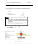
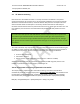
3.3 External Cable Connections
3.3.1.1 XMTR
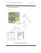
Please follow the diagram below:
1. Connect data cable - HARS0017 - from MASTER XMTR box to RB box
2. Connect data cable - HARS0017 - from SLAVE XMTR box to RB box
3. Connect data cable - HARS0018 - from MASTER XMTR box to TX SWITCH box
4. Connect data cable - HARS0018 - from SLAVE XMTR box to TX SWITCH box
5. Connect GPS cable - HARS0019 from MASTER XMTR box to TX SWITCH box
6. Connect GPS cable - HARS0019 from SLAVE XMTR box to TX SWITCH box
7. Connect RF cable - HARS0020 - from MASTER XMTR box to TX SWITCH box
8. Connect RF cable - HARS0020 - from SLAVE XMTR box to TX SWITCH box
9. Connect the grounding cable to the ground screw on the mounting kit
10. Connect the ETH+DC cable to the MASTER XMTR box
11. Connect the ETH+DC cable to the SLAVE XMTR box
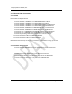
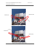
Note: Please allow drip loops for all cable connections (to avoid water running up into the
connectors.
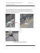
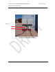
3.3.1.2 Weather box connection
1. Connect data cable HARS0021 – from the TX SWITCH box to the Weather box.
3.3.1.3 GPS Antenna and TX Connections
1. Add Polyphaser (Surge Suppression) on the GPS and TX antenna.
2. Connect the GPS antenna to the GPS antenna port of the TX SWITCH box
3. Connect Tx antenna cable to the “TX” port of the TX SWITCH box