
Installation Instructions

Document Name: WAPS BEACON Installation Manual
Version No: 1.4
Company Name: NextNav, LLC.
Confidential Page 20 11-Sep-12
Page 20 of 30
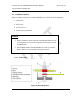
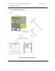
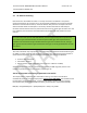
3.5 Connecting to the Power System
1. Open the Power System door
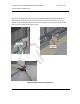
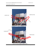
2. Switch the circuit breaker switches to the “off” position if not already.
3. Connect the HRS0016 cables
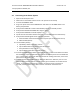
4. Plug in the power chord of the WAPS Beacon and switch on the MAIN switch in the
battery compartment
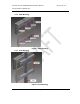
5. Verify that the GND tab is broken off and Battery switch is in the OFF position.
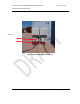
6. Verify that the Rectifier MiniPACK LED’s all go to green.
7. Verify that the MiniPACL controller display is on
8. Flip all three circuit breaker switches from step 3 to the ON position simultaneously.
9. Verify that the following LEDs are lit indicating operation:
a. Ethernet Switch: Phoenix Contact power and ports (all connected ports are lit)
b. EVDO modem (Raven)
10. Test the Battery backup
a. Flip Battery switch to the “ON” position
b. Flip the Main Switch from step 4 to the OFF position.
c. Verify all LEDs from step 7 are lit.
d. Flip the Main switch back to the ON position.
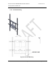
11. Connect the EvDO antenna cables to the EvDO Tx port. In cases of sites which have been
documented as requiring EvDO diversity, connect the diversity antenna to the EvDO DIV
port. In cases of sites which have been documented as needing a POTS line, connect the
phone line to the ‘TELCO’ port.
12. Connect the field service laptop with an Ethernet cable to the ‘Ethernet’ port on in the
Phoenix switch port #5. Wait for a few seconds to get an IP address on the field service
laptop. Try and browse the internet to ensure connectivity. Once connectivity is
ensured, call the operator at the NOC to further commission the beacon box.