
Installation Instructions

Document Name: WAPS BEACON Installation Manual
Version No: 1.4
Company Name: NextNav, LLC.
Confidential Page 29 11-Sep-12
Page 29 of 30
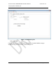
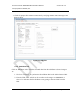
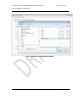
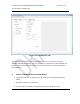
Figure 18: Power Amplifier Tab
After these steps, the beacon is commissioned with the correct output power levels (not
exceeding 30W ERP per channel), duty cycle, time slot(s), center frequency and bandwidth. The
GUI is then set to monitoring mode where each of the tabs report the measured parameters
from the beacon.
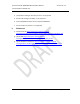
5 Known Limitations for the Socket Server
1. Image downloads are not supported through Socket Server (TX FPGA, RX FPGA, PA
FPGA)
2. Redundancy control is not supported
3. Communication to Rx FPGA is not supported (either through UART or SPI)