NEX-DDR3INTR-THIN DDR3 800/1066MT/s Interposer For use with the TLA7BB4 Logic Analyzer Modules Including these Software Support packages: B_DDR3D_2D (Single/Dual/Quad Rank, single slot with Selective Clocking) *B_DDR3D_2G (2 or 3 DIMM slots, two Rank @ 800MT/s) *B_DDR3D_3A (2 DIMM slots, two Rank @ 1066MT/s) * Optional Software Copyright © 2007 Nexus Technology, Inc. All rights reserved. Contents of this publication may not be reproduced in any form without the written permission of Nexus Technology, Inc.
Product Warranty Due to wide variety of possible customer target implementations, this product has a 30 day acceptance period by the customer from the date of receipt. If the customer does not contact Nexus Technology within 30 days of the receipt of the product, it will be said that the customer has accepted the product. If the customer is not satisfied with this product, they may return it within 30 days for a refund.
License Agreement In return for payment for this product, Nexus Technology grants the Customer a SINGLE user LICENSE in the software subject to the following: Use of the Software: - Customer may use the software on only one Tektronix mainframe logic analysis system at any given time - Customer may make copies or adaptations of the software (see Copies and Adaptations below for more information) - Customer may NOT reverse assemble or decompile the software Copies and Adaptations: - Are allowed for archival
TABLE OF CONTENTS 1.0 OVERVIEW ........................................................................................................................... 9 1.1 General Information ............................................................................................................ 9 1.2 Software Package description.............................................................................................. 9 1.3 Eye size required .....................................................................
B.3 TLA7BB4 Module to module skew.................................................................................. 75 APPENDIX C – 240-pin DDR3 DIMM Pinout ........................................................................... 76 APPENDIX D –Data Flow Through the Probes (coax cable to channel) .................................... 78 APPENDIX E – B_DDR3D_2D Support Pinout, DIMM Slot 0..................................................
TABLE OF FIGURES Figure 1 – Drawing of Interposer with probes attached ............................................................... 15 Figure 2 – Samtec connector on the LEASH probe...................................................................... 16 Figure 3 – LEASH probe to NEX-PRB1X/2X connection .......................................................... 17 Figure 4 - Read Data Latency = CAS Latency + CAS Additive Latency + RDIMM (5+0+1) = 6 cycles) ................................................
TABLE OF TABLES Table 1 - B_DDR3D_2D (<=1066MT/s Read and Write) TLA Channel Grouping.................... 19 Table 2 - B_DDR3D_2G (<=1066MT/s Read and Write) TLA Channel Grouping.................... 25 Table 3 - B_DDR3D_3A (<=1066MT/s Read and Write) TLA Channel Grouping.................... 31 Table 4 - B_DDR3D_2D/_2G TLA MagniVu Channel Grouping .............................................. 45 Table 5 - B_DDR3D_3A TLA MagniVu Channel Grouping ......................................................
DDR3THIN-MN-XXX 8 Doc. Rev. 1.
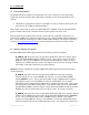
1.0 OVERVIEW 1.1 General Information The DDR3 Interposer Products are designed for ease of use. Interposers extra signal trace length, also an extra connector that might affect the quality of the system operation in some systems. • This Product is designed for capture of 1066MT/s or slower, and may only be used with the Tektronix TLA7BB4 acquisition modules. This product requires the use of the new NEX-PRB1X-T / PRB2X-T Low Profile Distributed probes available from Nexus.
NEX-DDR3INTR-THIN Interposer products. This support can be used with Single Rank and Dual Rank DIMMs. Note that this manual uses some terms generically. For instance, references to the TLA700/7000 apply to all suitable TLA700/7000 Logic Analyzers, or PCs being used to control the TLA. NEX-DDR3INTR-THIN refers to the B_DDR3D_2D/2G/3A software support packages. Appendix G has a silk-screened print of the NEX-DDR3INTR-THIN Logic Analyzer Interposer board.
1.3 Eye size required The Eye size (stable data) required at the input resistor to the Nexus passive probes (NEXPRB1X(-T) & NEX-PRB2X(-T)) is 330ps, and 0.2V. Capture accuracy may be affected if a stable eye can not meet this requirement. . The eye is a perfectly shaped diamond with each side equal distant from the center. 2.0 SOFTWARE INSTALLATION To Install the NEX-DDR3INTR-THIN software support place the B_DDR3D_XX Install CD in the CD drive of the TLA or the PC being used to control the TLA.
3.0 CONNECTING to the NEX-DDR3INTR-THIN INTERPOSER 3.1 General Care should be taken to support the weight of the acquisition probes so that the Logic Analyzer Interposer board and/or target socket are not damaged. 3.2 B_DDR3D_2D Support To acquire DDR3 Read and Write data at speeds up to 1066MT/s requires two merged TLA7BB4 136-channel, with 1.4G state option, acquisition cards and the use of the B_DDR3D_2D support software. The Master card will be in the lower numbered of the two cards.
TLA Master Connect the NEX-PRB1X-T “C” probe head to DDR3 Interposer’s LEASH (soldered-on coax cable) that is attached to “M_C” position on the Interposer. Connect the NEX-PRB2X-T A3/2 & A1/0 probe head to DDR3 Interposer’s LEASH that is attached to “M_ A3/2 A1/0” position on the Interposer. Connect the NEX-PRB1X-T “E” probe head to the NEX-PRBCOAX.
TLA Slave1 Connect the NEX-PRB2X-T A3/2 & A1/0 probe head to DDR3 Interposer’s LEASH that is attached to “S_ A3/2 A1/0” position on the Interposer. Connect the NEX-PRB2X-T “C3/2” & “E3/2” probe head to DDR3 Interposer’s LEASH that is attached to “S_C3/2 E3/2” position on the Interposer. TLA Slave2 Connect the NEX-PRB1X-T A3/2 D3/2 probe head to DDR3 Interposer’s LEASH that is attached to “M_A3/2 A1/0” position on the second Interposer.
3.5 Short “LEASH” probes The standard product includes 4 “LEASH” probes connected to this Interposer product. These short probes are soldered directly onto the interposer and interface the Interposer to the Passive probes that connect to the logic analyzer. These “LEASH” probes are to allow the user to easily install and remove the Interposer product in their system with out the added weight of the passive probe attached. There may be other probing options in the future. Contact Nexus for any updates.
The strain relief on the LEASH to NEXPRB1X/2X interface, while designed for bench handling, can be damaged by twisting the coax cables. Bends of over 45 degrees in this area should be avoided. The coax connection points, under any circumstances, are not to be bent. 3.5.1 Samtec connector on the LEASH probe pins Figure 2 – Samtec connector on the LEASH probe The LEASH probe connects to the NEX-PRB1X-T or NEX-PRB2X-T probe using two plastic nuts and screws, with a plastic spacer between the two boards.
3.5.2 LEASH probe to NEX-PRB1X/2X connection Probe tip on the NEX-PRB1X-T or NEX-PRB2X-T Interposer here Two each plastic Spacers Screws & Nuts Hold each probe together Transition board on the “LEASH” Cable end Figure 3 – LEASH probe to NEX-PRB1X/2X connection 3.5.3 Alternate use of NEX-PRB1X or NEX-PRB2X probes The NEX-PRB1X or NEX-PRB2X can be used in place of the “-T” probes but will have to be secured for long term connection by tie-wraps. DDR3THIN-MN-XXX 17 Doc. Rev. 1.
3.6 Slot Numbering The Interposer must be installed in the furthest slot from the memory controller. For 1066MT/s support only the two furthest slots may be used. Slots are named as shown below: Slot naming for a three slot system Memory controller Slot C Slot B cS0-1# cCLKE0-1 (from NEXPRBCOAX) Slot A bS0-1# S0-3# bCLKE0-1 CLKE0(from NEXPRBCOAX) If only one slot is used it must be the furthest slot from the memory controller.
Group Name RdA_DatHi (Hex) Signal Name RD_A_DQ63 RD_A_DQ62 RD_A_DQ61 RD_A_DQ60 RD_A_DQ59 RD_A_DQ58 RD_A_DQ57 RD_A_DQ56 RD_A_DQ55 RD_A_DQ54 RD_A_DQ53 RD_A_DQ52 RD_A_DQ51 RD_A_DQ50 RD_A_DQ49 RD_A_DQ48 RD_A_DQ47 RD_A_DQ46 RD_A_DQ45 RD_A_DQ44 RD_A_DQ43 RD_A_DQ42 RD_A_DQ41 RD_A_DQ40 RD_A_DQ39 RD_A_DQ38 RD_A_DQ37 RD_A_DQ36 RD_A_DQ35 RD_A_DQ34 RD_A_DQ33 RD_A_DQ32 DDR3 Pin # 234 233 228 227 115 114 109 108 225 224 219 218 106 105 100 99 216 215 210 209 97 96 91 90 207 206 201 200 88 87 83 81 TLA Input S_A2:0 S_A
Group Name RdB_DatHi (Hex) Signal Name DDR3 Pin# TLA Input RD_B_DQ63 RD_B_DQ62 RD_B_DQ61 RD_B_DQ60 RD_B_DQ59 RD_B_DQ58 RD_B_DQ57 RD_B_DQ56 RD_B_DQ55 RD_B_DQ54 RD_B_DQ53 RD_B_DQ52 RD_B_DQ51 RD_B_DQ50 RD_B_DQ49 RD_B_DQ48 RD_B_DQ47 RD_B_DQ46 RD_B_DQ45 RD_B_DQ44 RD_B_DQ43 RD_B_DQ42 RD_B_DQ41 RD_B_DQ40 RD_B_DQ39 RD_B_DQ38 RD_B_DQ37 RD_B_DQ36 RD_B_DQ35 RD_B_DQ34 RD_B_DQ33 RD_B_DQ32 234 233 228 227 115 114 109 108 225 224 219 218 106 105 100 99 216 215 210 209 97 96 91 90 207 206 201 200 88 87 83 81 S_A2:0^1
Group Name WrA_DatHi (Hex) Signal Name WR_A_DQ63 WR_A_DQ62 WR_A_DQ61 WR_A_DQ60 WR_A_DQ59 WR_A_DQ58 WR_A_DQ57 WR_A_DQ56 WR_A_DQ55 WR_A_DQ54 WR_A_DQ53 WR_A_DQ52 WR_A_DQ51 WR_A_DQ50 WR_A_DQ49 WR_A_DQ48 WR_A_DQ47 WR_A_DQ46 WR_A_DQ45 WR_A_DQ44 WR_A_DQ43 WR_A_DQ42 WR_A_DQ41 WR_A_DQ40 WR_A_DQ39 WR_A_DQ38 WR_A_DQ37 WR_A_DQ36 WR_A_DQ35 WR_A_DQ34 WR_A_DQ33 WR_A_DQ32 DDR3 Pin # 234 233 228 227 115 114 109 108 225 224 219 218 106 105 100 99 216 215 210 209 97 96 91 90 207 206 201 200 88 87 83 81 TLA Input S_D2:0 S_D
Group Name WrB_DatHi (Hex) Signal Name WR_B_DQ63 WR_B_DQ62 WR_B_DQ61 WR_B_DQ60 WR_B_DQ59 WR_B_DQ58 WR_B_DQ57 WR_B_DQ56 WR_B_DQ55 WR_B_DQ54 WR_B_DQ53 WR_B_DQ52 WR_B_DQ51 WR_B_DQ50 WR_B_DQ49 WR_B_DQ48 WR_B_DQ47 WR_B_DQ46 WR_B_DQ45 WR_B_DQ44 WR_B_DQ43 WR_B_DQ42 WR_B_DQ41 WR_B_DQ40 WR_B_DQ39 WR_B_DQ38 WR_B_DQ37 WR_B_DQ36 WR_B_DQ35 WR_B_DQ34 WR_B_DQ32 WR_B_DQ33 DDR3 Pin # 234 233 228 227 115 114 109 108 225 224 219 218 106 105 100 99 216 215 210 209 97 96 91 90 207 206 201 200 88 87 83 81 TLA Input S_D2:0^1 S
Group Name RdAChkBits (OFF) RdBChkBits 4 (OFF) ADatMsks (BIN) Signal Name RD_A_CB7 RD_A_CB6 RD_A_CB5 RD_A_CB4 RD_A_CB3 RD_A_CB2 RD_A_CB1 RD_A_CB0 RD_B_CB7 RD_B_CB6 RD_B_CB5 RD_B_CB4 RD_B_CB3 RD_B_CB2 RD_B_CB1 RD_B_CB0 A_DM7/DQS16 A_DM6/DQS15 A_DM5/DQS14 A_DM4/DQS13 A_DM3/DQS12 A_DM2/DQS11 A_DM1/DQS10 A_DM0/DQS9 DDR3 Pin # 165 164 159 158 46 45 40 39 165 164 159 158 46 45 40 39 230 221 212 203 152 143 134 125 TLA Input M_A1:5 M_A1:4 M_A1:0 M_A0:7 M_A1:6 M_A1:3 M_CK1 M_A0:5 M_A1:5^1 M_A1:4^1 M_A1:0^1 M_A
Group Name Control 2 (SYM) Strobes (HEX) Unprobed Signal Name CKE1 CKE0 S3# S2# S1# S0# BA2 BA1 BA0 A15 A14 A13 A12/BC# A10/AP RAS# CAS# WE# DQS7 DQS6 DQS5 DQS4 DQS3 DQS2 DQS1 DQS0 All DQSx# DDRCK1+/SA1 SDA SA0 SCL DDR3 Pin # 169 50 49 48 76 193 52 190 71 171 172 196 174 70 192 74 73 111 103 94 85 34 25 16 7 TLA Input M_A3:2 M_A3:1 M_C2:5 M_C3:0 M_C3:4 M_C3:3 M_A3:0 M_C3:7 M_C1:6 M_CK0 M_A2:5 M_CK3 M_A2:4 M_C1:3 M_C3:6 M_C3:5 M_C1:7 S_A2:6 S_A3:5 S_CK1 M_C2:3 M_A0:1 S_C3:0 S_E3:6 S_E2:4 Group Name Add
Group Name RdA_DatHi (Hex) Signal Name RD_A_DQ63 RD_A_DQ62 RD_A_DQ61 RD_A_DQ60 RD_A_DQ59 RD_A_DQ58 RD_A_DQ57 RD_A_DQ56 RD_A_DQ55 RD_A_DQ54 RD_A_DQ53 RD_A_DQ52 RD_A_DQ51 RD_A_DQ50 RD_A_DQ49 RD_A_DQ48 RD_A_DQ47 RD_A_DQ46 RD_A_DQ45 RD_A_DQ44 RD_A_DQ43 RD_A_DQ42 RD_A_DQ41 RD_A_DQ40 RD_A_DQ39 RD_A_DQ38 RD_A_DQ37 RD_A_DQ36 RD_A_DQ35 RD_A_DQ34 RD_A_DQ33 RD_A_DQ32 DDR3 Pin # 234 233 228 227 115 114 109 108 225 224 219 218 106 105 100 99 216 215 210 209 97 96 91 90 207 206 201 200 88 87 83 81 TLA Input S_A2:0 S_A
Group Name RdB_DatHi (Hex) Signal Name DDR3 Pin# TLA Input RD_B_DQ63 RD_B_DQ62 RD_B_DQ61 RD_B_DQ60 RD_B_DQ59 RD_B_DQ58 RD_B_DQ57 RD_B_DQ56 RD_B_DQ55 RD_B_DQ54 RD_B_DQ53 RD_B_DQ52 RD_B_DQ51 RD_B_DQ50 RD_B_DQ49 RD_B_DQ48 RD_B_DQ47 RD_B_DQ46 RD_B_DQ45 RD_B_DQ44 RD_B_DQ43 RD_B_DQ42 RD_B_DQ41 RD_B_DQ40 RD_B_DQ39 RD_B_DQ38 RD_B_DQ37 RD_B_DQ36 RD_B_DQ35 RD_B_DQ34 RD_B_DQ33 RD_B_DQ32 234 233 228 227 115 114 109 108 225 224 219 218 106 105 100 99 216 215 210 209 97 96 91 90 207 206 201 200 88 87 83 81 S_A2:0^1
Group Name WrA_DatHi (Hex) Signal Name WR_A_DQ63 WR_A_DQ62 WR_A_DQ61 WR_A_DQ60 WR_A_DQ59 WR_A_DQ58 WR_A_DQ57 WR_A_DQ56 WR_A_DQ55 WR_A_DQ54 WR_A_DQ53 WR_A_DQ52 WR_A_DQ51 WR_A_DQ50 WR_A_DQ49 WR_A_DQ48 WR_A_DQ47 WR_A_DQ46 WR_A_DQ45 WR_A_DQ44 WR_A_DQ43 WR_A_DQ42 WR_A_DQ41 WR_A_DQ40 WR_A_DQ39 WR_A_DQ38 WR_A_DQ37 WR_A_DQ36 WR_A_DQ35 WR_A_DQ34 WR_A_DQ33 WR_A_DQ32 DDR3 Pin # 234 233 228 227 115 114 109 108 225 224 219 218 106 105 100 99 216 215 210 209 97 96 91 90 207 206 201 200 88 87 83 81 TLA Input S_D2:0 S_D
Group Name WrB_DatHi (Hex) Signal Name WR_B_DQ63 WR_B_DQ62 WR_B_DQ61 WR_B_DQ60 WR_B_DQ59 WR_B_DQ58 WR_B_DQ57 WR_B_DQ56 WR_B_DQ55 WR_B_DQ54 WR_B_DQ53 WR_B_DQ52 WR_B_DQ51 WR_B_DQ50 WR_B_DQ49 WR_B_DQ48 WR_B_DQ47 WR_B_DQ46 WR_B_DQ45 WR_B_DQ44 WR_B_DQ43 WR_B_DQ42 WR_B_DQ41 WR_B_DQ40 WR_B_DQ39 WR_B_DQ38 WR_B_DQ37 WR_B_DQ36 WR_B_DQ35 WR_B_DQ34 WR_B_DQ32 WR_B_DQ33 DDR3 Pin # 234 233 228 227 115 114 109 108 225 224 219 218 106 105 100 99 216 215 210 209 97 96 91 90 207 206 201 200 88 87 83 81 TLA Input S_D2:0^1 S
Group Name RdAChkBits (OFF) RdBChkBits 4 (OFF) ADatMsks (BIN) Signal Name RD_A_CB7 RD_A_CB6 RD_A_CB5 RD_A_CB4 RD_A_CB3 RD_A_CB2 RD_A_CB1 RD_A_CB0 RD_B_CB7 RD_B_CB6 RD_B_CB5 RD_B_CB4 RD_B_CB3 RD_B_CB2 RD_B_CB1 RD_B_CB0 A_DM7/DQS16 A_DM6/DQS15 A_DM5/DQS14 A_DM4/DQS13 A_DM3/DQS12 A_DM2/DQS11 A_DM1/DQS10 A_DM0/DQS9 DDR3 Pin # 165 164 159 158 46 45 40 39 165 164 159 158 46 45 40 39 230 221 212 203 152 143 134 125 TLA Input M_A1:5 M_A1:4 M_A1:0 M_A0:7 M_A1:6 M_A1:3 M_CK1 M_A0:5 M_A1:5^1 M_A1:4^1 M_A1:0^1 M_A
Group Name Control 2 (SYM) Misc 2 (OFF) Unprobed Signal Name cCKE1 cCKE0 bCLK1 bCLK0 CKE1 CKE0 cS1# cS0# bS1# bS0# S3# S2# S1# S0# BA2 BA1 BA0 A15 A14 A13 A12/BC# A10/AP RAS# CAS# WE# MISC1 MISC0 DDRCK0+/All DQSx# DDRCK1+/SA1 SDA SA0 SCL DDR3 Pin # From Slot C From Slot C From Slot B From Slot B 169 50 From Slot C From Slot C From Slot B From Slot B 49 48 76 193 52 190 71 171 172 196 174 70 192 74 73 Placeholder Placeholder 184/185 TLA Input M_E3:5 M_E3:4 M_Q2 M_E1:7 M_A3:2 M_A3:1 M_E2:6 M_E2:2 M_E0:4
Group Name RdA_DatHi (Hex) Signal Name RD_A_DQ63 RD_A_DQ62 RD_A_DQ61 RD_A_DQ60 RD_A_DQ59 RD_A_DQ58 RD_A_DQ57 RD_A_DQ56 RD_A_DQ55 RD_A_DQ54 RD_A_DQ53 RD_A_DQ52 RD_A_DQ51 RD_A_DQ50 RD_A_DQ49 RD_A_DQ48 RD_A_DQ47 RD_A_DQ46 RD_A_DQ45 RD_A_DQ44 RD_A_DQ43 RD_A_DQ42 RD_A_DQ41 RD_A_DQ40 RD_A_DQ39 RD_A_DQ38 RD_A_DQ37 RD_A_DQ36 RD_A_DQ35 RD_A_DQ34 RD_A_DQ33 RD_A_DQ32 DDR3 Pin # 234 233 228 227 115 114 109 108 225 224 219 218 106 105 100 99 216 215 210 209 97 96 91 90 207 206 201 200 88 87 83 81 TLA Input S_A2:0 S_A
Group Name RdB_DatHi (Hex) Signal Name DDR3 Pin# TLA Input RD_B_DQ63 RD_B_DQ62 RD_B_DQ61 RD_B_DQ60 RD_B_DQ59 RD_B_DQ58 RD_B_DQ57 RD_B_DQ56 RD_B_DQ55 RD_B_DQ54 RD_B_DQ53 RD_B_DQ52 RD_B_DQ51 RD_B_DQ50 RD_B_DQ49 RD_B_DQ48 RD_B_DQ47 RD_B_DQ46 RD_B_DQ45 RD_B_DQ44 RD_B_DQ43 RD_B_DQ42 RD_B_DQ41 RD_B_DQ40 RD_B_DQ39 RD_B_DQ38 RD_B_DQ37 RD_B_DQ36 RD_B_DQ35 RD_B_DQ34 RD_B_DQ33 RD_B_DQ32 234 233 228 227 115 114 109 108 225 224 219 218 106 105 100 99 216 215 210 209 97 96 91 90 207 206 201 200 88 87 83 81 S_A2:0^1
Group Name 1_RdA_DatHi (Hex) Signal Name 1_RD_A_DQ63 1_RD_A_DQ62 1_RD_A_DQ61 1_RD_A_DQ60 1_RD_A_DQ59 1_RD_A_DQ58 1_RD_A_DQ57 1_RD_A_DQ56 1_RD_A_DQ55 1_RD_A_DQ54 1_RD_A_DQ53 1_RD_A_DQ52 1_RD_A_DQ51 1_RD_A_DQ50 1_RD_A_DQ49 1_RD_A_DQ48 1_RD_A_DQ47 1_RD_A_DQ46 1_RD_A_DQ45 1_RD_A_DQ44 1_RD_A_DQ43 1_RD_A_DQ42 1_RD_A_DQ41 1_RD_A_DQ40 1_RD_A_DQ39 1_RD_A_DQ38 1_RD_A_DQ37 1_RD_A_DQ36 1_RD_A_DQ35 1_RD_A_DQ34 1_RD_A_DQ33 1_RD_A_DQ32 DDR3 Pin # 234 233 228 227 115 114 109 108 225 224 219 218 106 105 100 99 216 215 210
Group Name 1_RdB_DatHi (Hex) Signal Name DDR3 Pin# TLA Input Group Name Signal Name DDR3 Pin# TLA Input 1_RD_B_DQ63 1_RD_B_DQ62 1_RD_B_DQ61 1_RD_B_DQ60 1_RD_B_DQ59 1_RD_B_DQ58 1_RD_B_DQ57 1_RD_B_DQ56 1_RD_B_DQ55 1_RD_B_DQ54 1_RD_B_DQ53 1_RD_B_DQ52 1_RD_B_DQ51 1_RD_B_DQ50 1_RD_B_DQ49 1_RD_B_DQ48 1_RD_B_DQ47 1_RD_B_DQ46 1_RD_B_DQ45 1_RD_B_DQ44 1_RD_B_DQ43 1_RD_B_DQ42 1_RD_B_DQ41 1_RD_B_DQ40 1_RD_B_DQ39 1_RD_B_DQ38 1_RD_B_DQ37 1_RD_B_DQ36 1_RD_B_DQ35 1_RD_B_DQ34 1_RD_B_DQ33 1_RD_B_DQ32 234 233 228 227
Group Name WrA_DatHi (Hex) Signal Name WR_A_DQ63 WR_A_DQ62 WR_A_DQ61 WR_A_DQ60 WR_A_DQ59 WR_A_DQ58 WR_A_DQ57 WR_A_DQ56 WR_A_DQ55 WR_A_DQ54 WR_A_DQ53 WR_A_DQ52 WR_A_DQ51 WR_A_DQ50 WR_A_DQ49 WR_A_DQ48 WR_A_DQ47 WR_A_DQ46 WR_A_DQ45 WR_A_DQ44 WR_A_DQ43 WR_A_DQ42 WR_A_DQ41 WR_A_DQ40 WR_A_DQ39 WR_A_DQ38 WR_A_DQ37 WR_A_DQ36 WR_A_DQ35 WR_A_DQ34 WR_A_DQ33 WR_A_DQ32 DDR3 Pin # 234 233 228 227 115 114 109 108 225 224 219 218 106 105 100 99 216 215 210 209 97 96 91 90 207 206 201 200 88 87 83 81 TLA Input S_D2:0 S_D
Group Name WrB_DatHi (Hex) Signal Name WR_B_DQ63 WR_B_DQ62 WR_B_DQ61 WR_B_DQ60 WR_B_DQ59 WR_B_DQ58 WR_B_DQ57 WR_B_DQ56 WR_B_DQ55 WR_B_DQ54 WR_B_DQ53 WR_B_DQ52 WR_B_DQ51 WR_B_DQ50 WR_B_DQ49 WR_B_DQ48 WR_B_DQ47 WR_B_DQ46 WR_B_DQ45 WR_B_DQ44 WR_B_DQ43 WR_B_DQ42 WR_B_DQ41 WR_B_DQ40 WR_B_DQ39 WR_B_DQ38 WR_B_DQ37 WR_B_DQ36 WR_B_DQ35 WR_B_DQ34 WR_B_DQ32 WR_B_DQ33 DDR3 Pin # 234 233 228 227 115 114 109 108 225 224 219 218 106 105 100 99 216 215 210 209 97 96 91 90 207 206 201 200 88 87 83 81 TLA Input S_D2:0^1 S
Group Name RdAChkBits (OFF) RdBChkBits 4 (OFF) 1_RdAChkBits (OFF) ADatMsks (BIN) Signal Name RD_A_CB7 RD_A_CB6 RD_A_CB5 RD_A_CB4 RD_A_CB3 RD_A_CB2 RD_A_CB1 RD_A_CB0 RD_B_CB7 RD_B_CB6 RD_B_CB5 RD_B_CB4 RD_B_CB3 RD_B_CB2 RD_B_CB1 RD_B_CB0 1_RD_A_CB7 1_RD_A_CB6 1_RD_A_CB5 1_RD_A_CB4 1_RD_A_CB3 1_RD_A_CB2 1_RD_A_CB1 1_RD_A_CB0 A_DM7/DQS16 A_DM6/DQS15 A_DM5/DQS14 A_DM4/DQS13 A_DM3/DQS12 A_DM2/DQS11 A_DM1/DQS10 A_DM0/DQS9 DDR3 Pin # 165 164 159 158 46 45 40 39 165 164 159 158 46 45 40 39 165 164 159 158 46 4
Group Name Control 2 (SYM) Strobes (HEX) Unprobed Signal Name CKE1 CKE0 S3# S2# S1# S0# BA2 BA1 BA0 A15 A14 A13 A12/BC# A10/AP RAS# CAS# WE# DQS7 DQS6 DQS5 DQS4 DQS3 DQS2 DQS1 DQS0 All DQSx# DDRCK1+/SA1 SDA SA0 SCL DDR3 Pin # 169 50 49 48 76 193 52 190 71 171 172 196 174 70 192 74 73 111 103 94 85 34 25 16 7 TLA Input M_A3:2 M_A3:1 S2_C2:5 S2_C3:0 M_C3:4 M_C3:3 M_A3:0 M_C3:7 M_C1:6 M_CK0 M_A2:5 M_CK3 M_A2:4 M_C1:3 M_C3:6 M_C3:5 M_C1:7 S_A2:6 S_A3:5 S_CK1 M_C2:3 M_A0:1 S_C3:0 S_E3:6 S_E2:4 Group Name A
3.7 Display Groups not in Tables 1,2 or 3 There are several groups in the List window that are not documented in the tables as these groups are used only by the post-processing display software. To ensure correct data display these groups must not be modified. These groups are: • • • • • • DataHi DataLo ChekBits Command DataMasks MRSAddr DDR3THIN-MN-XXX 39 Doc. Rev. 1.
4.0 CLOCK SELECTION 4.1 B_DDR3D_2D Clocking Selections There are two clocking option fields available when using the B_DDR3D_2D support package. These select fields permit the user to setup the TLA acquisition as follows: SDRAM Clocking: – Permits selecting the Clocking Mode to be used to acquire DDR3 data. It is important to note that the selection chosen will force unused Chip Selects and CKE1 into inactive states.
Latency of <= 5 cycles the support software will store a total of 13 clock cycles worth of data after the Read or Write Command appears on the bus. Refresh Cycles: – Permits choosing whether Refresh Cycles will be stored or not. The field choices are: Acquire (default) – Refresh Cycles will be stored. Do Not Acquire – This mode will reduce the number of Refresh cycles stored by the acquisition card to provide optimum use of the acquisition memory.
C:____B:_0__A:___0 0r1r1r – bS0# in the slot between the Interposer and the memory controller and S0# in the Interposer slot are active, equivalent to two Single Rank DIMMs. C:____B:_0__A:__10 0r1r2r – bS0#, S0# and S1# are active, equivalent to one Single Rank DIMM and one Dual Rank DIMM. C:____B:10__A:___0 0r2r1r – bS1#, bS0# and S0# are active, equivalent to a Dual Rank DIMM and a Single Rank DIMM. C:____B:10__A:__10 0r2r2r – bS1#, bS0#, S1# and S0# are active, equivalent to two Dual Rank DIMMs.
4.3 B_DDR3D_3A Clocking Selections There is one clocking option field available when using the B_DDR3D_3A support package. This select field sets up the TLA acquisition as follows: SDRAM DDR CLK0 Clocking: – Permits selecting the Clocking Mode to be used to acquire DDR3 data. Only one choice is available: Every Rising Edge – As the name implies this will cause the acquisition card to acquire data on every Rising edge of the DDR Clock 0. DDR3THIN-MN-XXX 43 Doc. Rev. 1.
5.0 CONFIGURING FOR READ / WRITE DATA ACQUISITION Prior to configuring your NEX-DDR3INTR-THIN support package it is strongly recommended that Appendix A (“How DDR Data is Clocked”), section 5.4 (“Selecting DDR Read Sample Points”) and section 5.5. (“Selecting DDR Write Sample Points”) be read. This background information is very helpful and facilitates proper support configuration. 5.
Group Name Data_H i Signal Name DQ63 TLA Input S_A2:0 DQ62 DQ61 DQ60 DQ59 DQ58 DQ57 DQ56 DQ55 DQ54 DQ53 DQ52 DQ51 DQ50 DQ49 DQ48 DQ47 DQ46 DQ45 DQ44 DQ43 DQ42 DQ41 DQ40 DQ39 DQ38 DQ37 DQ36 DQ35 DQ34 DQ33 DQ32 S_A2:1 S_A2:5 S_CK0 S_A2:2 S_A2:3 S_A2:7 S_A3:0 S_A3:2 S_A3:3 S_A3:7 S_A1:5 S_A3:1 S_A3:4 S_A1:7 S_A1:6 S_A1:4 S_A1:1 S_A0:7 S_A0:6 S_A1:3 S_A1:2 S_A0:5 S_A0:4 S_A0:3 S_A0:2 M_C2:1 M_C2:4 S_A0:1 S_A0:0 M_C2:6 M_C2:7 Group Name Data_L o Signal Name DQ31 TLA Input M_A0:6 DQ30 DQ29 DQ28 DQ27 DQ26
Group Name DataByte 7 DataByte 6 DataByte 5 DataByte 4 Signal Name DQ63 TLA Input S_A2:0 DQ62 DQ61 DQ60 DQ59 DQ58 DQ57 DQ56 DQ55 S_A2:1 S_A2:5 S_CK0 S_A2:2 S_A2:3 S_A2:7 S_A3:0 S_A3:2 DQ54 DQ53 DQ52 DQ51 DQ50 DQ49 DQ48 DQ47 S_A3:3 S_A3:7 S_A1:5 S_A3:1 S_A3:4 S_A1:7 S_A1:6 S_A1:4 DQ46 DQ45 DQ44 DQ43 DQ42 DQ41 DQ40 DQ39 S_A1:1 S_A0:7 S_A0:6 S_A1:3 S_A1:2 S_A0:5 S_A0:4 S_A0:3 DQ38 DQ37 DQ36 DQ35 DQ34 DQ33 DQ32 S_A0:2 M_C2:1 M_C2:4 S_A0:1 S_A0:0 M_C2:6 M_C2:7 Group Name DataByte 3 DataByte 2 Dat
Group Name CheckBit s Strobes 2 Control 2 Signal Name CB7 TLA Input M_A1:5 CB6 CB5 CB4 CB3 CB2 CB1 CB0 DQS8 DQS7 DQS6 DQS5 DQS4 DQS3 DQS2 DQS1 DQS0 CKE1 CKE0 S3# S2# S1# S0# BA2 BA1 BA0 A15 A14 A13 A12/BC# A10/AP RAS# CAS# WE# M_A1:4 M_A1:0 M_A0:7 M_A1:6 M_A1:3 M_CK1 M_A0:5 M_A1:2 S_A2:6 S_A3:5 S_CK1 M_C2:3 M_A0:0 S_C3:0 S_E3:6 S_E2:4 M_A3:2 M_A3:1 M_C2:5 M_C3:0 M_C3:4 M_C3:3 M_A3:0 M_C3:7 M_C1:6 M_CK0 M_A2:5 M_CK3 M_A2:4 M_C1:3 M_C3:6 M_C3:5 M_C1:7 Group Name DataMasks Address 2 Orphans Misc 2,5
Group Name Data_H i Signal Name DQ63 TLA Input S_A2:0 DQ62 DQ61 DQ60 DQ59 DQ58 DQ57 DQ56 DQ55 DQ54 DQ53 DQ52 DQ51 DQ50 DQ49 DQ48 DQ47 DQ46 DQ45 DQ44 DQ43 DQ42 DQ41 DQ40 DQ39 DQ38 DQ37 DQ36 DQ35 DQ34 DQ33 DQ32 S_A2:1 S_A2:5 S_CK0 S_A2:2 S_A2:3 S_A2:7 S_A3:0 S_A3:2 S_A3:3 S_A3:7 S_A1:5 S_A3:1 S_A3:4 S_A1:7 S_A1:6 S_A1:4 S_A1:1 S_A0:7 S_A0:6 S_A1:3 S_A1:2 S_A0:5 S_A0:4 S_A0:3 S_A0:2 M_C2:1 M_C2:4 S_A0:1 S_A0:0 M_C2:6 M_C2:7 Group Name Data_L o Signal Name DQ31 TLA Input M_A0:6 DQ30 DQ29 DQ28 DQ27 DQ26
Group Name DataByte 7 DataByte 6 DataByte 5 DataByte 4 Signal Name DQ63 TLA Input S_A2:0 DQ62 DQ61 DQ60 DQ59 DQ58 DQ57 DQ56 DQ55 S_A2:1 S_A2:5 S_CK0 S_A2:2 S_A2:3 S_A2:7 S_A3:0 S_A3:2 DQ54 DQ53 DQ52 DQ51 DQ50 DQ49 DQ48 DQ47 S_A3:3 S_A3:7 S_A1:5 S_A3:1 S_A3:4 S_A1:7 S_A1:6 S_A1:4 DQ46 DQ45 DQ44 DQ43 DQ42 DQ41 DQ40 DQ39 S_A1:1 S_A0:7 S_A0:6 S_A1:3 S_A1:2 S_A0:5 S_A0:4 S_A0:3 DQ38 DQ37 DQ36 DQ35 DQ34 DQ33 DQ32 S_A0:2 M_C2:1 M_C2:4 S_A0:1 S_A0:0 M_C2:6 M_C2:7 Group Name DataByte 3 DataByte 2 Dat
Group Name Data_Hi_1 Signal Name 1_DQ63 TLA Input S2_A0:0 1_DQ62 1_DQ61 1_DQ60 1_DQ59 1_DQ58 1_DQ57 1_DQ56 1_DQ55 1_DQ54 1_DQ53 1_DQ52 1_DQ51 1_DQ50 1_DQ49 1_DQ48 1_DQ47 1_DQ46 1_DQ45 1_DQ44 1_DQ43 1_DQ42 1_DQ41 1_DQ40 1_DQ39 1_DQ38 1_DQ37 1_DQ36 1_DQ35 1_DQ34 1_DQ33 1_DQ32 S2_A0:1 S2_A0:5 S2_CK1 S2_A0:2 S2_A0:3 S2_A0:7 S2_A1:0 S2_A1:2 S2_A1:3 S2_A1:7 S2_D1:5 S2_A1:1 S2_A1:4 S2_D1:7 S2_D1:6 S2_D1:4 S2_D1:1 S2_D0:7 S2_D0:6 S2_D1:3 S2_D1:2 S2_D0:5 S2_D0:4 S2_D0:3 S2_D0:2 S2_C2:1 S2_C2:4 S2_D0:1 S2_D0:0 S2
Group Name DataByte7_ 1 DataByte6_ 1 DataByte5_ 1 DataByte4_ 1 Signal Name 1_DQ63 TLA Input S2_A0:0 1_DQ62 1_DQ61 1_DQ60 1_DQ59 1_DQ58 1_DQ57 1_DQ56 1_DQ55 S2_A0:1 S2_A0:5 S2_CK1 S2_A0:2 S2_A0:3 S2_A0:7 S2_A1:0 S2_A1:2 1_DQ54 1_DQ53 1_DQ52 1_DQ51 1_DQ50 1_DQ49 1_DQ48 1_DQ47 S2_A1:3 S2_A1:7 S2_D1:5 S2_A1:1 S2_A1:4 S2_D1:7 S2_D1:6 S2_D1:4 1_DQ46 1_DQ45 1_DQ44 1_DQ43 1_DQ42 1_DQ41 1_DQ40 1_DQ39 S2_D1:1 S2_D0:7 S2_D0:6 S2_D1:3 S2_D1:2 S2_D0:5 S2_D0:4 S2_D0:3 1_DQ38 1_DQ37 1_DQ36 1_DQ35 1_DQ34 1_DQ33
Group Name ChkBits Strobes 2 DataMasks Control 2 Misc 2,5 Signal Name CB7 CB6 CB5 CB4 CB3 CB2 CB1 CB0 DQS8 DQS7 DQS6 DQS5 DQS4 DQS3 DQS2 DQS1 DQS0 DM7 DM6 DM5 DM4 DM3 DM2 DM1 DM0 CKE1 CKE0 S3# S2# S1# S0# BA2 BA1 BA0 A15 A14 A13 A12/BC# A10/AP RAS# CAS# WE# MISC1 MISC0 DDRCK0 TLA Input M_A1:5 M_A1:4 M_A1:0 M_A0:7 M_A1:6 M_A1:3 M_CK1 M_A0:5 M_A1:2 S_A2:6 S_A3:5 S_CK1 M_C2:3 M_A0:0 S_C3:0 S_E3:6 S_E2:4 S_A2:4 S_A3:6 S_A1:0 M_C2:0 M_A0:2 S_CK3 S_E3:5 S_E2:6 M_A3:2 M_A3:1 S2_C2:5 S2_C3:0 M_C3:4 M_C3:3 M_A
5.3 Adjusting Input Thresholds for Proper Data Acquisition The Interposer DDR3 support was designed to work with the new Nexus Low Profile Distributed probes. To maximize the electrical characteristics of the acquired waveforms the probe input resistors values were placed at 510 ohms. This value results in a divide by ten of the signals to the logic analyzer when using the NEX-PRB1X-T and NEX-PRB2X-T probes. The logic analyzer expects a divide by 20.
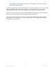
Sample Pt. #2 Sample Pt. #1 Figure 4 - Read Data Latency = CAS Latency + CAS Additive Latency + RDIMM (5+0+1) = 6 cycles) 5.6 Selecting B_DDR3D_XX Write Data Sample Points Unlike valid DDR Read data, valid Write data is bisected by the Strobes. Since valid DDR3 Write data is bisected by the Strobes (see Figure 5) the Setup & Hold sample point must be set for the valid data that occurs closest to the clock edge.
The B_DDR3D_XX supports acquire two samples of valid Write data on each rising edge of the DDR3 clock. So to acquire both pieces of data the WrA_DatHi/Lo data groups must have their sample point set to that shown by Sample Pt. #1 in the Figure, and the WrB_DatHi/Lo data groups must have their sample point set to that shown by Sample Pt. #2.
A B Figure 7 - Measuring B_DDR3D_XX RdA_DatHi / Lo Read Data Setup & Hold Zoom in further to determine the Setup and Hold sample point necessary to acquire valid data at that point (Figure 7) and use the cursors to measure the time from the clock edge to the start of valid Read data. In this example the delay from edge to data is approximately -1.05ns after the clock edge, meaning that a suitable Setup & Hold value for the RdA_DatHi capture group would be -1.055ns/1.289ns.
A B Figure 8 - Measuring B_DDR3D_XX RdB_DatHi / Lo Read Data Setup & Hold Now the sample point positions must be set for the RdA_DatHi, RdA_DatLo, RdB_DatHi and RdB_DatLo capture groups in the Setup window (see Figure 9). This window is found by going to the LA Card’s Setup window, then clicking on the More button to the right of the clock select field. The TLA acquisition cards require a valid data window of approximately 300ps, and this window can be placed to begin from 15.
Setting the Setup & Hold values for acquiring Write data is a similar process. To determine the Write Data group sample points first make an appropriate acquisition of Write data by triggering on a Write Command. Then, as above, create a timing window display of MagniVu data and display the Data_Hi and Data_Lo 32-bit data groups, the individual Command group signals and the DDR3 clock that was used for the data acquisition (DDRCK0). A sample waveform display of MagniVu Write data is shown in Figure 10.
A B Figure 11 - Measuring B_DDR3D_XX WrA_DatHi / Lo Write Data Setup & Hold Now the sample point for the WrB_DatHi and WrB_DatLo groups must be determined (see Figure 12). The next valid Write data (after the cycle measured above) occurs approximately 500ps after the rising edge of DDRCK0, so a suitable Setup & Hold value for the WrB_DatHi capture group would be -508ps/742ps. As with the A data the Data_Lo group is somewhat later than the Data_Hi group.
used as Data Masks then the WrtMasks group should have a Setup & Hold value that matches that of the Write Data groups. Figure 13 - Setting B_DDR3D_XX WrA_DatHi / Lo and WrB_DatHi / Lo Sample Points Because of the speeds of DDR3 data it may be necessary to program Setup & Hold values for each of the 8-bit groups that are associated with a given Strobe. This could be required if there is significant skew between the DDR Strobes.
Figure 14 - Viewing Individual 8-bit Read Data Groups Figure 15 - Setting Individual Setup & Hold Values for the 8-bit Read Data Groups Note: Values shown are for illustration purposes only DDR3THIN-MN-XXX 61 Doc. Rev. 1.
5.8 Setting B_DDR3D_3A Read Data Sample Points The same procedure outlined above for setting Read Data sample points should be used to determine the sample points for Read Data from teh second DIMM slot. Set the sample points for the groups named RdA_DatHi_1, RdA_DatLo_1, RdB_DatHi_1 and RdB_DatLo_1. DDR3THIN-MN-XXX 62 Doc. Rev. 1.
6.0 VIEWING DATA 6.1 Viewing B_DDR3D_XX Data When using the NEX-DDR3INTR-THIN support packages the raw Address and Data groups are suppressed and are replaced with post-processed data in new groups. This data is displayed in new groups that have the support package name preceding it (i.e., B_DDR3D_XX Address, B_DDR3D_XX DataHi, etc.). The raw data groups are suppressed so that the display of data can be done in a more user-friendly fashion.
To change the display it is necessary to bring up the window’s Properties window (perform a right mouse-click in the State display window) and select the Disassembly tab. This will bring up the configuration window shown in Figure 17. Figure 17 - Disassembly Properties There are several select fields available in this window, some of which must be set correctly for the post-processing software to work properly.
DM Signal Use - permits setting Data Mask functionality to Write Masks (default) or Strobes. When set to Write Mask the DM signals will be used to mask Write Data to show which data bytes were valid in the cycle.
data are displayed. Note that the timestamp is updated to reflect the time between displayed cycles. 6.2 Viewing Raw DDR3 Data using B_DDR3D_XX Supports In order to make the display of DDR3 data more user-friendly the raw data from the Address, all Data and other groups is suppressed in the B_DDR3D_2D Listing display. Instead the postprocessing display software formats and reorders the data to tag and display valid DDR3 Address, Commands and Data.
Table 7 gives a brief description of each of the text lines displayed in the B_DDR3D_2G postprocessing software display.
Figure 19 - B_DDR3D_XX MagniVu Display on TLA DDR3THIN-MN-XXX 68 Doc. Rev. 1.
7.0 HINTS & TIPS 7.1 Symbolic Triggering on a Command using B_DDR3D_XX Supports A Symbol Table has been included for the Control data groups defined in each of the support packages. The Symbol Table for the B_DDR3D_2D / 3A supports is shown in Table 8; the Symbol Table for the B_DDR3D_2G support is shown in Table 9. The use of Symbol Tables when triggering makes it easier for the user to define a given cycle to be triggered on.
Symbol Definition cccc ssssssss = xxxxx1 1110 for S0# cccc ssssssss = xxxx1x 1101 for S1# cccc ssssssss = xxxxx1 1011 for S2# cccc ssssssss = xxxx1x 0111 for S3# cccc ssssssss = xxxxx1 1110 for bS0# cccc ssssssss = xxxx1x 1101 for bS1# cccc ssssssss = xxxxx1 1011 for cS0# cccc ssssssss = xxxx1x 0111 for cS1# x in Definition = Don’t Care MRS – Sx# MODE REGISTER SET cccc ssssssss xxx xxx xx000 MRS – bSx# MODE REGISTER SET cccc ssssssss xxx xxx xx000 MRS – cSx# MODE REGISTER SET cccc ssssssss xxx xxx xx000 R
Figure 20 - B_DDR3D_2D MRS Trigger In the trigger example a Storage condition has been created so that only MRS cycles will be stored. In testing, multiple MRS cycles were seen during the boot process, and the example triggers shown will ensure that all of the MRS cycles will be acquired, an example of which is shown in Figure 20. The last acquired MRS cycle will reflect the settings used in the DDR target – in this case, a CAS latency of 2 cycles with a Burst length of 8.
the differential pair by removed. The added capacitance of the logic analyzer compensates for this missing capacitor. 7.5 Thresholds Analog waveforms and their associated thresholds viewed using the Tektronix Analog Mux will display amplitudes and thresholds that are not an exact representation of the actual analog waveform.
APPENDIX A – How DDR Data is Clocked A.1 Background Demultiplexing means that the TLA’s Logic Analyzer card can have one data probe connected to the target yet store incoming data in two or four separate data sections of the card. For instance, the A3 data section (8-bits) can be connected to the target and data can be stored in the A3 section and the D3 section.
A.3 B_DDR3D_2D / 2G / 3A Data Acquisition These supports requires two (2) merged 136-channel with 1.4G state option TLA7BB4 acquisition cards used in a TLA7XX logic analyzer. Data is acquired using the rising edge of the DDR clock. A_Data information is earlier (older) data than the information stored in B_Data. Different Sample Points must be set for each of the four 32-bit Data groups, and, if necessary, sample points can be set for any of the 8-bit data groups or for individual data bits.
APPENDIX B - Considerations B.1 NEX-DDR3INTR-THIN Bus Loading It must be noted that the NEX-DDR3INTR-THIN Interposer is designed to minimal effect on the user’s circuit. The acquired signals are sampled at top edge connector, and then passed through isolation resistors to the probe. There will be an effective 600 ohm load on all probed signals. The B_DDR3D_3A support will use two Interposers and will double probe all signal. Thus the DC load will be near 300 ohms.
APPENDIX C – 240-pin DDR3 DIMM Pinout Pin # 1 2 3 4 Front Side (left 1-60) X64 X72 NonECC Parity VREF VREF VSS VSS DQ0 DQ0 DQ1 DQ1 Back Side (right 121-180 Pin # X64 Non-Parity X72 ECC 121 122 123 124 VSS DQ4 DQ5 VSS DM0 DQS9 NC DQS9# VSS VSS DQ4 DQ5 VSS DM0 DQS9 NC DQS9# VSS 5 VSS VSS 125 6 DQS0# DQS0# 126 7 DQS0 DQS0 127 Front Side (left 61-120) X64 X72 Pin # NonECC Parity 61 A2 A2 62 VDD VDD 63 CK1 CK1 64 CK1# CK1# 65 VDD Back Side (right 181-240) X64 X72 Pin # NonECC Parity 181 A1
APPENDIX C - 240-pin DDR3 DIMM Pinout (cont’d.
APPENDIX D –Data Flow Through the Probes (coax cable to channel) Data flow Slave1 C3/2/1/0 Master A3/2 D3/2 Master C3/2/1/0 Slave1 A3/2 D3/2 Slave1 E3/2/1/0 Master A1/0 D1/0 Slave1 A1/0 D1/0 Plastic Housing that plugs into TLA 7BB4 Samtec Connectors plug together at this point J15-x Coax on top J16-x Coax on J16-1 edge J15-1 edge Master A3/2 & Slave1 C3/2 & E3/2 DDR3THIN-MN-XXX Interposer Slave1 A3/2 & A1/0 Master 78 Doc. Rev. 1.
APPENDIX D - Data Flow Through the Probes (cont’d.
APPENDIX E – B_DDR3D_2D Support Pinout, DIMM Slot 0 Samtec Pin Coax Pin 15 29 25 28 24 21 19 20 16 12 10 11 9 6 4 5 3 46 32 36 33 37 40 J15-6 J15-10 J15-9 J16-11 J16-12 J15-8 J15-7 J16-13 J16-14 J16-15 J16-16 J15-5 J15-4 J16-17 J16-18 J15-3 J15-2 J16-6 J16-10 J16-9 J15-11 J15-12 J16-8 TLA Channe l CK1 A1:7 A1:6 A1:5 A1:4 A1:3 A1:2 A1:1 A1:0 A0:7 A0:6 A0:5 A0:4 A0:3 A0:2 A0:1 A0:0 CK0 A3:7 A3:6 A3:5 A3:4 A3:3 42 41 45 J16-7 J15-13 J15-14 A3:2 A3:1 A3:0 49 51 50 52 55 57 56 58 DDR3 Signal CB1 NC CB3
APPENDIX E – B_DDR3D_2D Support Pinout, DIMM Slot 0 (Cont’d.
APPENDIX F – B_DDR3_2G Support Pinout, DIMM Slot 0 Auxiliary Signals Samte c Pin Coax Pin TLA Channe l 46 32 36 J16-6 J16-10 J16-9 E3:7 E3:6 33 J15-11 E3:5 37 40 42 41 45 49 J15-12 J16-8 J16-7 J15-13 J15-14 J15-15 E3:4 E3:3 E3:2 E3:1 E3:0 E2:7 51 50 52 55 J15-16 J16-5 J16-4 J15-17 E2:6 E2:5 E2:4 E2:3 57 56 58 J15-18 J16-3 J16-2 E2:2 E2:1 E2:0 15 J15-6 Q2 29 25 28 24 21 19 20 16 12 10 11 J15-10 J15-9 J16-11 J16-12 J15-8 J15-7 J16-13 J16-14 J16-15 J16-16 J15-5 E1:7 E1:6 E1:5 E1:4 E1:3
DDR3THIN-MN-XXX 83 Doc. Rev. 1.
APPENDIX G – B_DDR3D_3A Support Pinout, DIMM Slot 1 Samte c Pin Coax Pin 15 29 25 28 24 21 19 20 16 12 10 11 9 6 4 5 3 46 32 36 33 37 40 42 41 45 J15-6 J15-10 J15-9 J16-11 J16-12 J15-8 J15-7 J16-13 J16-14 J16-15 J16-16 J15-5 J15-4 J16-17 J16-18 J15-3 J15-2 J16-6 J16-10 J16-9 J15-11 J15-12 J16-8 J16-7 J15-13 J15-14 TLA Channe l Q0+ D3:7 D3:6 D3:5 D3:4 D3:3 D3:2 D3:1 D3:0 D2:7 D2:6 D2:5 D2:4 D2:3 D2:2 D2:1 D2:0 CK0+ A3:7 A3:6 A3:5 A3:4 A3:3 A3:2 A3:1 A3:0 DDR3 Signal CB1 NC CB3 CB7 CB6 CB2 DQS8 DM8 CB5
APPENDIX G – B_DDR3D_3A Support Pinout, DIMM Slot 1 (cont’d.
APPENDIX H – Data Group / Data Byte / Strobe Cross-Reference 32-bit Data Group RdADatHi RdADatLo WrADatHi WrADatLo RdBDatHi RdBDatLo WrBDatHi WrBDatLo 8-bit Data Group RdADatB7 RdADatB6 RdADatB5 RdADatB4 RdADatB3 RdADatB2 RdADatB1 RdADatB0 WrADatB7 WrADatB6 WrADatB5 WrADatB4 WrADatB3 WrADatB2 WrADatB1 WrADatB0 RdBDatB7 RdBDatB6 RdBDatB5 RdBDatB4 RdBDatB3 RdBDatB2 RdBDatB1 RdBDatB0 WrBDatB7 WrBDatB6 WrBDatB5 WrBDatB4 WrBDatB3 WrBDatB2 WrBDatB1 WrBDatB0 Strobe DQS7 DQS6 DQS5 DQS4 DQS3 DQS2 DQS1 DQS0
APPENDIX I – NEX-DDR3INTR-THIN Silkscreen Front Silk-screen DDR3THIN-MN-XXX 87 Doc. Rev. 1.
APPENDIX J – Keep out area DDR3THIN-MN-XXX 88 Doc. Rev. 1.
APPENDIX K – Simulation Model Double this if you are using two Interposers on the same memory channel DDR3THIN-MN-XXX 89 Doc. Rev. 1.
APPENDIX L - References JEDEC PC3-6400/PC3-8500-10660 DDR3 SDRAM Unbuffered DIMM Design Specification Revision 0.1 March 20, 2006. Tektronix TLA7000 Series Installation Manual Tek part number 071-1747-03 Tektronix TLA7000 Series Technical Reference Manual Tektronix part number 071-1764-00 Nexus Low Profile Distributed Probe Manual— Part number LowProfileProbes-MN-XXX JEDEC DDR3 SDRAM Standard JESD79-3 June 2007 DDR3THIN-MN-XXX 90 Doc. Rev. 1.
APPENDIX M - Support About Nexus Technology, Inc. Established in 1991, Nexus Technology, Inc. is dedicated to developing, marketing, and supporting Bus Analysis applications for Tektronix Logic Analyzers. We can be reached at: Nexus Technology, Inc. P.O. Box 6575 Nashua, NH 03063 TEL: 877-595-8116 FAX: 877-595-8118 Web site: http://www.nexustechnology.com Support Contact Information Technical Support General Information Quote Requests techsupport@nexustechnology.com support@nexustechnology.