
Computer Hardware User Manual

DDR3THIN-MN-XXX 71 Doc. Rev. 1.11
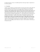
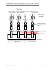
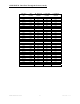
Figure 20 - B_DDR3D_2D MRS Trigger
In the trigger example a Storage condition has been created so that only MRS cycles will be
stored. In testing, multiple MRS cycles were seen during the boot process, and the example
triggers shown will ensure that all of the MRS cycles will be acquired, an example of which is
shown in Figure 20. The last acquired MRS cycle will reflect the settings used in the DDR target
– in this case, a CAS latency of 2 cycles with a Burst length of 8.
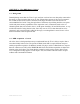
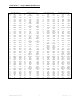
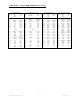
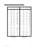
Figure 21 - MRS Cycle Acquisition Disassembly
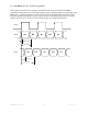
7.4 Clock Capture quality
The clock captured by the logic analyzer may exhibit ringing. If this ringing is such that a clock
reference voltage can not be determined it is suggested that the capacitor on the DIMM across