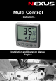
Multi Control - Instrument - Installation and Operation Manual English English
MULTI CONTROL 1
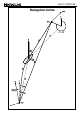
MULTI CONTROL Navigation terms 2
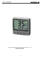
MULTI CONTROL This manual is written for NX2 Multi Control version 3.1 – 5.
MULTI CONTROL 1 2 Part specification ....................................................................... 8 Installation................................................................................ 12 2.1 Installing the instrument ...............................................................................13 2.1.1 Installing instrument to the Server............................................................14 3 First start .......................................................................
MULTI CONTROL 7.7 7.8 8 Silencing an alarm ....................................................................................... 25 Turning off / on an alarm............................................................................. 25 NAVIGATION functions............................................................26 8.1 NAVIGATION main-function ........................................................................ 26 8.2 NAVIGATION sub-functions ....................................................
MULTI CONTROL 12.2.3 C22 ( - 00.0 ADJ) .................................................................................41 12.2.4 C23 (Unit°C) ........................................................................................41 12.2.5 C24 (0°C TMP) ....................................................................................41 12.2.6 C25 (Unit hPA).....................................................................................41 12.3 C30, calibration of navigation .........................
MULTI CONTROL 12.7.2 Change NMEA sentences OUT from Server ....................................... 50 12.7.3 Receive NMEA sentences IN to Server............................................... 51 12.8 Special NMEA sentences ............................................................................ 53 12.8.1 Baudrate control, ................................................................................. 53 13 Maintenance and fault finding.................................................54 13.
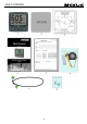
MULTI CONTROL 1 Part specification ___________________________________________________________ Items delivered with the instrument 1 1 5 5 4 4 1 1 1 2 1 1 1 1 1 1 1 NX2 Multi Control instrument Instrument cover Cable protectors, 0,25 mm (0.1 inch) Cable protectors, 0,75 mm (0.
MULTI CONTROL 9
MULTI CONTROL Welcome aboard the Nexus Network! Thank you for choosing NX2 and welcome to the world of the Nexus Network. Through this manual we would like to help you install, operate and understand your new Nexus Network. The Server is the ”heart” of your Nexus Network, to which transducers for speed, depth, heading, wind and navigation (GPS, Loran or Decca) are connected.
MULTI CONTROL 11
MULTI CONTROL 2 • 1. 2. 3. 4. 5. 6. Installation The installation includes 6 major steps: Read the installation and operation manual. Plan where to install the transducers and instruments. Run the cables. Install the transducers and instruments. Take a break and admire your installation. Learn the functions and calibrate your system. Before you begin drilling ... think about how you can make the installation as neat and simple as your boat will allow.
MULTI CONTROL 2.1 Installing the instrument • Place the adhesive drill template on the desired location for the instrument. Drill the 2 holes using a 5 mm (1/4") drill for the two pin bolts. Use a 63 mm (2½") hole saw to machine the clearance hole for the instrument connection socket. Remove the template.
MULTI CONTROL • • Apply silicon paste to the instrument connection pins at the back of the instrument. Press the jack plug onto the instrument pins. Press the cable in to the cable leads. Mount the connection back cover with the screw. 2.1.1 Installing instrument to the Server All NX2 instruments are connected directly to the Nexus Network in a daisy chain. They all use the same colour coded 4-pole jack plugs.
MULTI CONTROL 3 First start 3.1 Initialising the instrument At power on, the instrument will perform a self test. The display will first show all segments, then the software version number and the Nexus Network ID number. er installation, you will be asked to press SET At first power on after (PrESkey). This will give the instrument a logical ID number on the Nexus Network. To initialise the instrument, press SET on all installed digital instruments, one at the time.
MULTI CONTROL 4 Operation 4.1 About this manual • In this manual each time a push-button is refereed to, the push-button name will appear in bold and CAPITAL letters example PAGE. • Unless otherwise momentary. • Each time a function is mentioned in the text, it will be in brackets and in the same format, where possible, as displayed, ex. (LAt). • By the word navigator, we mean a GPS, Loran or Decca instrument.
MULTI CONTROL 4.2 How to use the push-buttons PAGE SIGN MAIN FUNCTION SUB FUNCTION CLEAR 4.2.1 MINUS PLUS PAGE PAGE A press on PAGE moves the top LCD arrow to the next page. It scrolls in a circular pattern, one step to the right for every press, in the order SPEED, DEPTH, NAVIGATE, WIND and then back to SPEED page again. A press on PAGE and MINUS together, back steps PAGE to the preceding page. The PAGE button is also used to move the cursor when in edit mode.
MULTI CONTROL In edit mode it increases to the next digit. 4.2.4 SET A press on SET unlocks a digit to access edit mode. When unlocked, the digits are ”active” (flashes) and can be edited by pressing MINUS, PLUS and PAGE as required. When finished editing, lock the digit by another press on SET. 4.2.5 Clear / cancel / reset A press on CLEAR, clear digits, cancel alarms or resets the counters. 4.2.6 Calibration To access calibration mode, press and hold SET more than 2 seconds.
MULTI CONTROL 5 Function overview The functions in the Multi Control instrument are divided into 4 pages: SPEED, DEPTH, NAVIGATE and WIND. The selected page is indicated by the LCD arrow at top of the display. Each page has 2 types of functions that can be displyed together: 1. Main-function, displayed at the top of the display in 30 high digits. 2. Sub-function, displayed at the bottom part of the display in 17 mm high digits.
MULTI CONTROL 6 SPEED functions 6.1 SPEED main-function Boat speed through the water. Unit available in knots (KT), km/h (Kh) or miles/h (Mh) (See 12.1.2, C11). If a navigator is connected, speed over ground (SOG) can be displayed. (See 12.6.11,C95). 6.2 SPEED sub-functions 6.2.1 TRIP LOG (TRP) 0-199,99 NM, only displayed in NM. Distance covered from power on. To reset TRIP LOG press CLEAR. 6.2.2 TOTAL LOG (LOG) 0-19999 NM, only displayed in NM. Can not be reset. 6.2.
MULTI CONTROL 6.2.8 DEPTH (unit/DPT) Depth from the water surface or the keel depending on calibration setting (See 12.2.3, C22). Unit available in meters (m), feet (FT) or fathoms (FA). (See 12.2.2,C21). The text alternates between the selected (unit) and (DPT).
MULTI CONTROL 7 PLUS functions General information Alarm on = minute sign ( ´ ) displayed above the last depth digit in the sub-function. Alarm off = no minute sign ( ´ ) displayed. The alarms will be triggered, if the actual depth becomes less (shallow alarm), or more (depth alarm), than the set depth value. The alarm is audible (signal) and visual (main and sub-function flashes).
MULTI CONTROL 7.2.2 BATTERY (BAT) Battery voltage at the Server. 7.2.3 SHALLOW ALARM (SHA) Depth at which point audible and visual alarms will be triggered, if the actual depth becomes less than the set value. (See 7.4). 7.2.4 DEPTH ALARM (DEA) Depth at which point audible and visual alarms will be triggered, if the actual depth becomes more than the set value. (See 7.4). 7.2.
MULTI CONTROL 7.3 Remote Control (REM) The NX2 Multi Control can be used to remote control other digital NX2 instruments. All digital NX2 instruments has their unique ID number on the Nexus Network. At power up the ID numbers are displayed for a short time. The instrument to the right has ID number 16 (version number is 2.0) Note the ID numbers for the instrument you want to remote control. Press SET and the selected ID number is flashing.
MULTI CONTROL 7.4 Set and turn on shallow (SHA) and depth alarm (DEA) Select shallow (SHA) or depth (DEA) alarm, press SET. The first digit in the previous value flashes. If you want to reset the previous value to zero (0), Press CLEAR. To select desired depth press MINUS, PLUS and PAGE as required. Press SET to lock the selected value. By this last press on SET, you have turned on the selected alarm function, which is indicated by the minute sign ( ´ ) above the last depth digit in the sub-function. 7.
MULTI CONTROL 8 NAVIGATION functions 8.1 NAVIGATION main-function Heading 000° to 359°. Heading true (HT) or heading magnetic (HM) can be displayed if the compass transducer is connected. (See 12.3.11 C40) If a navigator is connected, course over ground (CG) can be selected instead of compass heading. (See 12.6.10, C94). Note! This page can either be on or off. As a factory setting this page is automatically on if a Compass transducer or GPS is connected.
MULTI CONTROL To stop alternating, press SET. To restart alternating, press SET again. 8.2.6 SET and DRIFT Direction of current (SET) and speed of current (DRF). Alternating function. To stop alternating, press SET. To restart alternating, press SET again. 8.2.7 (CMG) and (DMG) Course made good (CMG) and distance made good (DMG) The function is based on the principle of dead reckoning.
MULTI CONTROL steer your boat so that the display readout is 0.00 NM, which means you are on the desired track. 8.3 Steer reference (Pilot) The sub-function (Pilot) is intended to be used together with the optional analogue instrument steer pilot (Art. No. 20550-2) to assist the helmsman to keep the desired heading. The powerful combination of the Multi Control instrument together with the analogue steer pilot actually offers you 6 functions. Compass steering: (MEM) 1.
MULTI CONTROL The last used steer reference function will be stored in memory and automatically activated at power on. (Available Server version 2.6) 8.3.
MULTI CONTROL in (Pilot OFF) function. (Available from Server software version 1.9.) 8.3.3 Steer reference (BTW) This function requires the NX2 or NMEA compass transducer and a NX2 GPS or NMEA navigator. When selected, the function displays (BTW) and the analogue steer pilot instrument displays the difference between the compass heading and the bearing to waypoint (BTW). The function can only be displayed if the connected navigator is navigating towards a waypoint.
MULTI CONTROL 8.3.4 Steer reference (CTS) This function requires log transducer, NX2 or NMEA compass transducer , NX2 GPS or NMEA navigator. When selected the function displays (CTS) and the analogue steer pilot instrument displays the difference between the compass heading and the bearing to waypoint (CTS) including set and drift. The function can only be displayed if the connected navigator is navigating towards a waypoint.
MULTI CONTROL The underlining sign ( _ ) = starboard side. The minus sign ( - ) = port side. To select value, press MINUS, PLUS and PAGE as required. To store the value, press SET. When the steer reference function (AWA) is used together with the analogue steer pilot instrument, you can display an enlarged ”picture” of the tacking or run angle. Put simply, you ”expand” the wind angle. Use the analogue steer pilot as a ”close hauled” instrument.
MULTI CONTROL 9 Wind functions 9.1 WIND Main-function Apparent wind angle (AWA), true wind angle (TWA) 000° - 359°, apparent wind speed (AWS) or true wind speed (TWS): Note! This page can either be on or off. As a factory setting this page is automatically on if a Compass transducer or GPS is connected. In the set up, you can select this page to be on, off or automatic on. See chapter: 12.5.2 The main-function WIND, allows you to display wind angle or wind speed, true or apparent.
MULTI CONTROL 9.2.3 APPARENT WIND SPEED (AWS) Units displayed in m/s (m/s), knots (KTS) or Beaufort (BF), (see 12.5.4, C53). The function alternates between (AWS) and the selected (units). 9.2.2 TRUE WIND ANGLE (TWA) This function requires a log transducer. The he complimenting function to what is displayed in the main function is displayed. If the main function is set to display apparent wind angle (AWA), the true wind angle (TWA) will be displayed here.
MULTI CONTROL 9.2.7 GEOGRAPHIC WIND DIRECTION This function requires a compass transducer. Displays the direction in 000° to 359° and the each cardinal point abbreviation as shown: 000.0° = N 022.5° = NNE 045.0° = NE 067.5° = ENE 090.0° = E 112.5° = ESE 135.0° = SE 157.5° = SSE 180.0° = S 202.5° = SSW 225.0° = SW 247.5° = WSW 270.0° = W 292.5° = WNW 315.0° = NW 337.5° = NNW If magnetic heading is selected, geographic wind direction will also be magnetic direction. (See 12.3.
MULTI CONTROL 9.3 Tactical function This function requires a compass transducer and displays course memory. One for starboard and one for port tack. To fully use the tactical function it is recommended to install the optional trim button (Art. No. 19763) and analogue steer pilot instrument (Art. No 22115-02). The trim button is usually installed close to the steering position. Many prefer to install one trim button on each side of the boat, that is one for each tack.
MULTI CONTROL (or the trim button). When you tack, the reference value of the last leg will automatically be displayed. If the optional analogue steer pilot instrument connected, select sub-function pilot (MEM), as steer reference (See 8.3.2). The deviation from selected course will be displayed on the analogue steer pilot instrument. If you do not have the optional trim button or analogue steer pilot connected, we suggest you move the sub-function (TAC) to the NAVIGATE page.
MULTI CONTROL Distance to the MOB position will be displayed in the sub-function. All you have to do is to keep calm and steer the boat in the indicated direction and distance to pick up your wet crew member. To reset the (MOB) function, press CLEAR. The earlier calculated course (CMG) and the distance made good (DMG) is not affected by the (MOB) function.
MULTI CONTROL the sub-function (TWS) will be displayed. The copied sub-function remains in its original location. It is only copied to a second location, where it takes the place of the empty sub-function in the list. Note: The sub-function damping (SEA) should not be moved, to avoid misunderstanding. 11.3 Select power on function The last selected combination of page and sub-functions according to your selection in 11.1 is the first page the instrument will display at power up. 11.
MULTI CONTROL 12 Calibration To get the most out of your Nexus Network, it is important to carefully calibrate the Network. The calibration values are stored in a non volatile memory. To access calibration mode, press and hold SET more than 2 seconds. To select a calibration code, press MINUS, PLUS and PAGE as required. To return to normal mode, press SET when the text return (RET) is displayed.
MULTI CONTROL 12.1.4 C13 DAMPING (SEA) Damping of indicated boat speed through the water. Controls the response time of speed changes. To change damping, press SET. To select damping level, press PLUS and select from: d0 (Min) to d9 (max). To store the value, press SET. Default value is (d0), for use in calm sea. But if the sea is rough, you may want to ”stabilise” the readout on the display, then select (d1) to (d9). Note! Damping is set separately for each instrument. 12.2 C20, calibration of depth 12.2.
MULTI CONTROL 12.3 C30, calibration of navigation 12.3.1 C30 (RET) To return to the normal mode, press SET. 12.3.2 C31 (PAGE ATO) This setting allows you to display the Navigate page or not. PAGE ATO Page automatically on if Compass transducer or GPS is connected PAGE ON Page is always on PAGE OFF Page is always off 12.3.3 C32 (00° OCA) Off Course Alarm. Can be set between 00°and 99° (00°) = Alarm is turned off. 12.3.4 C33 (00.0 VAR) Magnetic variation. Maximum +/- 99.9°.
MULTI CONTROL (Available for analogue steer pilot instruments, from version 1.3). 12.3.11 C40 (OFF MAG) (Available from Multi version 2.0) (ON) = All headings and bearings will be magnetic. (OFF) = All headings and bearings will be true. Note a: In the (Goto WP) function, the bearing for every leg will always be displayed as true bearing. Note b: The setting is only affects the independent Multi Control instrument in which is set. 12.3.12 C41 DAMPING (SEA) Damping of compass heading.
MULTI CONTROL Note: You will get the best result in calm water with a smooth turn on the steering wheel independently of how the circle is performed. When activated, you can stop the automatic compass deviation at any time with a press on CLEAR. 12.4.2 Automatic compass deviation check (Auto CHK) (Auto CHK) is done by driving the boat in a circle up to 1 ¼ turn, after (Auto DEV) is performed. The result will be compared with (Auto DEV).
MULTI CONTROL 12.5 C50, calibration of wind 12.5.1 C50 (RET) To return to the normal mode, press SET. 12.5.2 C51 (PAGE ATO) This setting allows you to display the Navigate page or not. PAGE ATO Page automatically on if Compass transducer or GPS is connected PAGE ON Page is always on PAGE OFF Page is always off 12.5.3 C52 (OFF TWA) Select true (TWA)or the apparent wind angle (AWA) as mainfunction under WIND. The optional analogue wind instrument will display the same selection.
MULTI CONTROL C59 (180° 180) C60 (225° 225) C61 (270° 270) C62 (315° 315) to the calibration certificate. 12.5.8 C64 (WIA) Select from 5 functions. (WIA) is the factory setting. Select the function to be displayed as main-function under WIND. The optional analogue wind instrument will display the same selection. Select from 5 functions. (WIA) is the factory setting. If the selected main-function is an angle, the sub-function will show the complimenting angle, e.g.
MULTI CONTROL 12.5.10 C67 WIND SPEED ALARM (WSA) To set a wind speed alarm level. The buzzer will sound when the true wind speed is higher than the set level. To switch of the alarm, set C67 to 00. To silence an alarm, press any key. The alarm level is set from 1 to 50 m/s. To set the alarm level, press SET. To select level, press PAGE, PLUS or MINUS as required. To store the selected value, press SET.
MULTI CONTROL 12.6.6 C75 (OFF CMP) (OFF) = NX2 compass transducer. (On) = NMEA compass transducer. If you want to use a NMEA transducer (connected to the NMEA input, you have to set C75 to On. The Server will then transmit this information on the Nexus Network to all connected instruments. After you have changed this setting, you have to restart the system 12.6.7 C76 (OFF WND) (OFF) = NX2 wind transducer. (On) = NMEA wind transducer.
MULTI CONTROL 12.7 NMEA 12.7.1 Transmit NMEA sentences OUT from Server Calibration code C77 to C92 contains 16 NMEA slots The Server supports 29 different NMEA sentences. This means you can select up to 16 of the 29 available NMEA sentences. The Nexus Network uses the NMEA 0183 sentences, version 1.5 and 2.0. The number in brackets, example (C79), is the calibration code for the factory slot number given to the NMEA sentence.
MULTI CONTROL Example of NMEA sentences: $IIAPA,A,A,00.007,L,N,V,V,145.03,M,004 $IIAPB,A,A,00.007,L,N,V,V,147.53,T,004,147.52,T,,T*29 $IIBOD,147.53,T,145.03,M,004,000 $IIBWC,101515,5912.890,N,01812.580,E,147.52,T,145.02,M,15.649,N,004 $IIBWC,,,,,,147.52,T,145.02,M,15.647,N,004 $IIBWR,101516,5912.890,N,01812.580,E,147.52,T,145.02,M,15.647,N,004 $IIDBT,293.52,f,089.47,M,048.36,F $IIDPT,089.47,0.40 $IIGLL,5926.110,N,01756.171,E,101517,A $IIHDM,026,M $IIHDT,029,T $IIMTW,19,C $IIMWD,161.77,T,159.27,M,07.01,N,03.
MULTI CONTROL other 8 slots with even numbers, C78, C80, C82 ... C92 free to use for other NMEA sentences. For connection of NMEA instruments OUT from Server, (see Server manual). 12.7.3 Receive NMEA sentences IN to Server There are 6 different main types of NMEA sentences: 1) Position related data: Position, SOG/COG, time, and a limited amount of satellite status if a GPS is connected. The information is read if no other Nexus GPS is connected. If a Nexus GPS is connected, it will take over the navigation.
MULTI CONTROL TBS CAD CFD RSA Target boat speed Custom angular data Custom fix data Rudder Sensor Angle For connection of NMEA instrument IN to Server, (see Server Manual). All data (POSITION, BTW, SOG/COG, etc.) is received from one type of NMEA sentence. If data is placed in different locations, the data will be selected from the sentence with the highest priority. Example I: Position is read in priority order: GGA, GLL and. RMC. Example II: BTW/DTW is priority first with: RMB, BWC and BWR.
MULTI CONTROL 12.8 Special NMEA sentences The Server can read 2 special NMEA sentences which can be send from a PC. One contains TBS (target boat speed), the other CAD (customised angle data ) and CFD (customised fixpoint data ). These 3 data are retransmitted on the Nexus Network and can be displayed as a sub-function on the Multi Control instrument. To get the sub-function TBS, select main function SPEED and the ”empty” subfunction.Then press PAGE and SET together followed by CLEAR.
MULTI CONTROL 13 Maintenance and fault finding 13.1 Maintenance • • • • • To clean the instrument, use only mild soap solution and rinse with water. Do not use detergents or high pressure washing equipment. At least once a year, check all your connections and apply additional silicon paste at each connection point. Always use the instrument cover for protection, when not in use.
MULTI CONTROL 13.2.2 Fault - action 1. Speed and distance functions: No reading ( --- ) - C95 (COG) should be OFF, if no navigator is connected. For more information, see manual for NX2 Server. Irregular values: Check the speed damping (SEA), (see 12.1.4). 2. Compass: No reading ( --- ) − C75 should be OFF, if no NMEA compass is connected. − Make sure the (Auto DEV) routine is done correctly, (see 12.4.1) − Make sure the transducer is not mounted upside down. − The transducer cable should face down.
MULTI CONTROL 14 Specifications 14.1 Technical specifications Dimensions: Instrument cable: Multi Control instrument: 113 x 113 x23 mm (4.3x4.3 inch). Server: 110 x 165 x 30 mm. (4.3x6.5x1.2 inch) 8 m (26 ft). Power supply: Power consumption at 12V: 12V DC (10-16V). The instruments are polarity protected Temperature range: Storage:-30°to +80°C (-22°to +176°F) Operation: -10° to +70°C(14°to +158°F) Multi Control instrument: 260 gram (9.17 oz). Server: 220 gram. (7.76 oz).
MULTI CONTROL 14.3 Optional Accessories Below find a selection of optional accessories available. Please contact your local NX2 dealer for more information.
MULTI CONTROL 21680-1 21684-1 69995 Nexus Multi XL Multi XL instrument, 4m cable (RCI or Multi Center needed to control Multi XL) Multi XL Set, Multi XL instrument and Remote Control instrument Mast bracket XL, in aluminium for Multi XL and Nexus / Star 110x110mm instr.
MULTI CONTROL 14.4 Abbreviations Abbreviation.
MULTI CONTROL GLL Geographic Latitude Longitude GoTo GPS HDM HDT HM HT id Init Insert Km KT KTS L LAT LCD LGD LOG LON LOW MAX m/s MEM Mh MID MN MOB m N NAV NM NMEA NXT OCA RET Roll S S/A SAT SEA SEC SET SHA SOG STA Go To Global Positioning Network HeaDing Magnetic HeaDing True Heading Magnetic Heading True Identity Initiation Insert Kilometre per hour KnoTs KnoTS Local LATitude Liquid Crystal Display Local Geodetic Datum LOG LONgitude LOW MAX metres per second MEMory Miles per hour MID Magnetic North Man
MULTI CONTROL STR SW TAC TMP TRP TTG TWA TWS UTC VAR VMG W WCV WP XTE _ STeeR South West TACtical TeMPerature TRiP Time To Go True Wind Angle True Wind Speed Universal Time Co-ordinate VARiation Velocity Made Good West Waypoint Closure Velocity Waypoint Cross Track Error Minus Plus Wind from port side Wind from starboard side The boat is left of the desired track The boat is right of the desired track 61
MULTI CONTROL 15 Warranty WARRANTY GENERAL All our products are designed and built to comply to the highest class industry standards. If the products are correctly installed, maintained and operated, as described in the installation and operation manual, they will provide long and reliable service. Our international Network of distributors can provide you with the information and assistance you may require virtually anywhere in the world.
MULTI CONTROL File id: WARRANTY CARD TO BE RETURNED TO YOUR NATIONAL DISTRIBUTOR OWNER: Name: Street : City/Zip Code : Country: Product name: Serial number: A B C 1 2 3 4 5 6 7 Date of purchase: _______________ Date installed ________________ Dealers stamp: Tick here if you do not wish to receive news about future products 63
MULTI CONTROL 64
MULTI CONTROL 65
MULTI CONTROL 66
Copyright ©: Nexus Marine AB Kuskvägen 4, 191 62 Sollentuna, Sweden Tel: +46 -(0) 8 – 506 939 00. Fax: +46 -(0) 8 -506 939 01 www.nexusmarine.