
Installation Guide


3
Parts List, continued
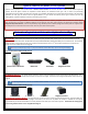
Cables
Motor Cables (3) – Black cable with white, six-pin plugs. Use these cables to connect the Lift Columns to the Control Box
(using slots #1, #2, and #3 on the Control Box). There are 3 Cables total, in 2 different sizes, 4.5m and 2.5m.
Power Cable – Connects Control Box to power outlet. Three feet long.
RF Cable (only present if you ordered the RF version of the Lift System) – Use to connect the RF Receiver to the Control
Box. Ends have RJ-45 connectors. One foot long.
Hardware
13. Eight (8) – 5mm x 12mm Flat Head Machine Screw
14. Six (6) – 6mm x 12mm Flat Head Machine Screw
15. Four (4) -- 6mm x 16mm Flat Head Machine Screw
16. Twelve (12) – 6mm x 20mm Flat Head Machine Screw
17. Sixteen (16) – 6mm x 10mm Button Head Machine Screw
19. Eight (8) -- 6mm x 12mm Button Head Machine Screw
20. Four (4) -- 3/8 - 16 x ¾” Button Head Machine Screw
21. Two (2) -- Screen Locks (In bag labeled PDM-0108)
22. Four (2) -- 1½” x ¼” Steel Threaded Taper Pins (For Floating Top)
23. Two (2) -- #10 x 1 ¾” Flat Head Wood Screw (For Backup Switch)
24. Thirty-Six (36) -- #10 x ¾” Truss Head Wood Screw
25. Two (2) -- #8 x ¾” Flat Head Wood Screw (For IR controls only)
26. RF Controls or IR Controls (see explanation on page 5)
27. Three (3) -- Allen Wrenches –3mm, 4mm and 7/32”
28. Four (4) -- Square Multi Mount Washers
29. Four (4) – Lid Catch Brackets w/ (8) #10 x ¾” THWS
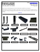
Control Box
Top Support Brackets
Assorted Hardware
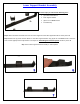
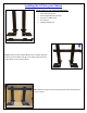
Long & Short Cable
Management Track