
User's Manual

SYSTEM CONNECTIONS:
CONTROL AMPLIFIER INPUT SECTION:
SPEAKER CABLE CONNECTIONS:
CAUTION:
CAUTION:
MAKE ALL CONNECTIONS WITH THE AC POWER OFF!
CONNECTING THE OUTPUT OF THE A-20 CONTROL AMPLIFIER TO ANY
EQUIPMENT OTHER THAN THE A-20 OR C-20 MONITOR MAY CAUSE
EQUIPMENT DAMAGE.
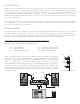
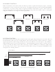
The A-20 Control Amplifier accepts both balanced and unbalanced inputs on either XLR or 1/4” TRS connectors. These
connectors are hardwired in parallel within the A-20 to allow for convenient equipment chaining, but only one signal source
should be physically connected to the unit at any time. Figure 3a shows the proper wiring schematic for each type of
connector. Since there are so many different connector types and signal levels employed by source equipment, some
experimentation may be necessary, keeping in mind that the A-20 can accept a wide range of signals and has an
input sensitivity control on the front panel.
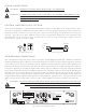
The A-20 includes two 20’ special purpose cables to connect the Control amplifier to the Monitors. While these cables look
similar to standard microphone cables, they are constructed with lower and more consistent conductor impedance. Portions
of the A-20’s crossover circuitry are located in both the amplifier and speaker enclosures, and the cables supplied are an
important part of this electrical network. This allows the speaker cables to function as a neutral and transparent component
in the system. Replacing or extending the supplied cables with any other type will have a varying, and only partly predictable
impact on the sound of the A-20. If your installation requires the use of alternative cables, you may consult the table listing our
measurement data on a variety of cable types at www.vergenceaudio.com under the support section. Be sure they are wired as
shown in Fig. 3a. These considerations aside, using the Vergence cables to connect the control amplifier is quite simple and
straight forward. Both the amplifier and the monitors are marked with the appropriate “left” and “right” channels. Fit the
XLR connectors into the corresponding connectors on the control amplifier and monitors until the connector locks.
WARNING: IF USING CABLES OTHER THAN THOSE SUPPLIED WITH THIS SYSTEM, BE SURE
THAT NO CONDUCTIOR IS WIRED TO THE XLR CASING. FAILURE TO
DO SO MAY CONSTIT UTE A RISK OF ELECTRIC SHOCK.
2
3
1
TRS
1
3
2
XLR
PIN SIGNALPIN SIGNAL
1
2
3
GND
+
_
Fig. 3a Balanced Wiring Diagram
1
2
3
+ (SIGNAL)
- (GND)
Shield
SOURCE
A-20 INPUT
Fig. 3b Unbalanced Wiring Diagram
NHTPro
MODEL A-20 CONTROL AMPLIFIER.
SERIAL NO:
NHTPro
BENICIA, CALIFORNIA, U.S.A.
A20-A-10001
MADE IN TAIWAN
G1
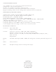
CAUTION:
CONNECTING OUTPUTS TO ANY
PRODUCT OTHER THAN A-20 or
C-20 MONITORS MAY RESULT IN
SEVERE EQUIPMENT DAMAGE.
INPUT
RIGHT
LEFT
2
3
1
TRS
1
3
2
XLR
PIN SIGNALPIN SIGNAL
1
2
3
GND
+
_
U
L
LISTED
AUDIO EQUIP
LISTED
AUDIO
EQUIP
FUSE TYPE:
T9A 250V FOR 110/120V.
T5A 250V FOR 220/240V.
50/60 Hz - 950W
INPUT VOLTAGE
CAUTION
RISK OF ELECTRIC SHOCK
DO NOT OPEN
WARNING: SHOCK HAZARD-DO NOT OPEN.
AVIS: RISQUE DU CHOC ELECTRONIQUE-
NE PAS OUVRIR.
FOR CONTINUED PROTECTION AGAINST
RISK OF FIRE REPLACE ONLY WITH SAME
TYPE 250V FUSE.
CAUTION:
A-20 Monitor
Right
A-20 Monitor
Right
A-20 Monitor
Left
A-20 Monitor
Left
Fig. 4 A-20 Control Amplifier Rear Panel