® Pro Audio M-20 Powered Monitor Owner’s Manual M-20 Control Amplifier Serial Number: M-20 Monitor Serial Number: Rev. 6.
Safety Instructions -- Please Read First CAUTION: To reduce the risk of electric shock, do not remove the cover (or back). No user serviceable parts are inside; refer servicing to qualified personnel. WARNING: To reduce the risk of fire or electric shock, do not expose this appliance to rain or moisture. This symbol wherever it appears, alerts you to the presence of uninsulated dangerous voltage inside the enclosure that may be sufficient to constitute a risk of electric shock.
INTRODUCTION: Thank you for selecting and purchasing the M-20. Your studio monitors are a critical element in the countless decisions made during recording, mixing, and mastering and must deliver a transparent, neutral sound so you have the information you need to choose and place microphones, set eq’s, balance mixes; ie, to deliver exceptional product. Multiple M-20’s deliver state-of-the-art multi channel monitoring capability.
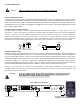
SYSTEM CONNECTIONS: CAUTION: MAKE ALL CONNECTIONS WITH THE AC POWER TURNED OFF! POWER CONNECTIONS/FUSE: The power cord receptacle contains a spare fuse located within the power connector. To get at the fuse, remove the power cord and use a small flat head screwdriver to access the fuse compartment. When replacing the fuse with a spare, use only a fuse of the same current rating.
USING THE M-20 CONTROL FUNCTIONS: The M-20 controls are designed for utility and repeatability under varying conditions and make only subtle impact on the basic character and accuracy of the speaker. We encourage you to experiment with fine tuning the system to your particular requirements. CONTROL M-20 AMPLIFIER Fig. 5 M-20 Control Amplifier Front Panel POWER INDICATORS: Two LED’s are located to the immediate left of the power switch on the M-20 Control Amplifier:.
BOUNDARY CONTROL: Reflective boundaries, such as floors, walls, even table tops, reinforce a speaker’s low frequency output. Conversely, placing speakers out into a room decreases bass response. The greatest low frequency output is with the BOUNDARY control in the “0” position, which assumes no significant boundary reinforcement is present. Each control step attenuates low frequencies by 1.5 dB (at 50 Hz), with rapidly decreasing effect above 300 Hz. Refer to the diagram in Fig.
SPEAKER PLACEMENT: The M-20 Monitor System is intended to provide consistent performance over a wide range of placement situations. This is accomplished through the use of electrical controls, wide dispersion drivers, advanced enclosure design and carefully chosen crossover characteristics. Nevertheless, it is always worth investing time and effort experimenting with optimum loudspeaker placement. In all cases, the M-20 Monitors should be set up the same distance from the listening position. (see fig.
SYSTEM SPECIFICATIONS: SYSTEM/MONITOR: Type: Modular, two piece powered near/mid/far field monitor. Configuration: 2-way acoustic suspension. Woofer: 6.5" curvilinear treated paper. Butyl surround. Tweeter: 1" metal dome, textile surround, ferro-fluid cooled and damped. Magnetic Shielding: Full Loudspeaker Dimensions/Wgt.: 14" h x 8" w x 9.375” d, 19 lbs. Shipping weight: 22lbs./10 kg. Loudspeaker Materials: 0.75" MDF. CONTROL AMPLIFIER: Amplifier Power: 250W (continuous rms), 400W (100ms peak).