Niagara Video B264 openGear® Encoder B264 Standalone Encoder User Manual Version 2.
Copyright © 2016 Niagara Video Corporation. All rights reserved. Contents of this publication may not be reproduced in any form without the written permission of Niagara Video. Notice The material in this manual is furnished for informational use only, and it is subject to change without notice. It must not be construed as a commitment by Niagara Video. Niagara Video assumes no responsibility or liability for errors or inaccuracies that may appear in this manual.
Company Address Niagara Video Corporation 5627 Stoneridge Drive Suite 316 Pleasanton, CA 94588 USA Telephone +1 925 399 7201 E-mail (Technical Support): E-mail (General Information): Website: support@niagara-video.com sales@niagara-video.com http://www.niagara-video.
Contents Copyright ........................................................................................................................................ 2 Notice .............................................................................................................................................. 2 Trademarks ..................................................................................................................................... 2 Environmental Information .............................
Encoder Advanced Configuration Tab ................................................................................. 43 Advanced Tab – Video Parameters................................................................................... 44 Advanced Tab – VBI/Ancillary Data Insertion ................................................................ 46 Advanced Tab – Audio Parameters .................................................................................. 49 Advanced Tab – Additional Audio Channels ...
Control Port Configuration Tab .............................................................................................. 110 Control Port Statistics Tab ...................................................................................................... 111 SNMP Configuration Tab ....................................................................................................... 112 SNMP Statistics Tab ................................................................................................
Safety Instructions for the Appliances The Niagara Video appliances are turned off by using the power switch. Power may still be present in the appliance. To ensure that the appliance is completely shut down, unplug its power cord from its power source. The Niagara Video appliances ship with all required components installed. There is no need to open the chassis to add or remove components. Please contact Niagara Video regarding any malfunction or failure of the Niagara Video appliance.
CE Mark Warning This is a Class A product. In a domestic environment, this product may cause radio interference, in which case the user may be required to take adequate measures. Installation Safety Notes Do not place the Niagara Video appliances underneath heavy loads or in an unstable position. Do not expose the Niagara Video appliances under direct sunlight, high humidity or wet conditions.
For USA and Canada: The cord set must be UL-approved and CSA-certified. The attachment plug must be an earth-grounding type with a NEMA 5-15P (15A 125V) plug and an EN60320/IEC320 receptacle.
Introduction This manual covers the following products: The B264 openGear® H.264 SD/HD single and dual-channel encoder card The B264 standalone H.264 SD/HD single and dual-channel encoder appliance Both products have the same set of features, and essentially the same user interface. Unless specifically indicated, all features and controls described in this manual apply to all products.
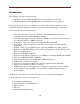
Product Overview The B264 supports up to two H.264 SD/HD encoders, with up to four stereo pairs of audio encoding. One stereo pair is dedicated to each video encoder, and the remaining two stereo pairs can be individually associated with either channel. The encoded transport stream can be routed and replicated to Ethernet and ASI outputs. Both SPTS and MPTS outputs are supported.
Outputs Inputs ASI 1 Composite/SDI A/V 1 Unbalanced Audio A/V 2 Mux ETH1 Composite/SDI ASI 2 Switch Unbalanced Audio Encoder 1 ETH2 Up to 4 Encoder 2 Switch Up to 4 Test Generator Test Generator For the remainder of this manual, we will use the term port for a physical input/output port (such as ASI or Ethernet), and stream for a transport stream present in the port. ASI ports support only one stream, while Ethernet ports support multiple streams.
B264 Indicators and Switches The B264 card can be installed in the 10-slot DFR-8310 frame, or in the 20-slot DFR-8321 or OG3-FR frames. Prior to installing the card, first install the corresponding rear panel I/O module. Note that the rear I/O panel for the DFR-8321 and OG3-FR frames is different from the panel for the DFR-8310; if you have the wrong panel, please contact Niagara Video to have it replaced1.
VID2 VID1 VID2 ASI1 ASI2 ASI1 ASI2 + G _ R G _ G _ + ETH1 AUD1 LFT AUD2 LFT AUD1 RT AUD2 RT + AUD2 G _ L R AUD1 L VID1 + ETH1 ETH2 ETH2 Unbalanced Audio Balanced Audio Note that the balanced audio rear I/O panel is only supported boards with hardware version 4 and higher. The hardware version is available in the Product Tab in DashBoard. Front Indicators A similar set of indicators exist in the front of the board. These are visible when the frame front door is opened.
stopped (either by explicit configuration or by lack of input) or if it is in one of the Web streaming modes (HTTP Live Streaming or Direct HTTP Streaming). ETH1 and ETH2 LEDs: these indicate the status of the corresponding Ethernet connection. o Off: no link o On: link OK, no activity o Blinking: link OK, port is transmitting and/or receiving packets Top Corner Status Power OK VID 2 VID 1 ASI 2 ASI 1 ENC 2 ENC 1 ETH 2 ETH 1 The B264 board has other LEDs that may or may not be illuminated.
the switch. You can release the switch once the Status LED turns orange. This action causes the card to revert to the factory-default firmware. Reset Switch: Pressing this pushbutton switch causes the card to reset.
B264 Indicators and Switches The B264 can be used as a desktop encoder, or in a 19” rack-mount tray that holds up to three units: Back Panel The B264 ships with one of two possible back panels: Unbalanced Audio Back Panel Balanced Audio Back Panel The panels are depicted in the next page.
Balanced Audio Version L AUD1 R ASI1 VID1 L AUD2 R ASI2 VID2 I 0 + - G + - G CTRL1 ETH1 CTRL2 ETH2 + Control Ethernets - G + - G Streaming Ethernets Each of the video inputs has a green indicator LED, with the following states: LED off: no video signal detected, or input not configured. LED flashing: video input locked to the video signal. o LED flashing about once per second: input video is SD. o LED flashing about twice per second: input video is HD-SDI.
PWR CH1 CH2 STAT VID ASI ENC CTL ETH The front panel LED indicators are as follows: STAT: indicates the overall status of the unit. o Green: no active alarm o Red: at least one critical alarm present When powering up the unit, this LED will be red until the board starts operation. At that point, it will turn green if there is no active alarm or stay red if there is at least one alarm. PWR: indicates that the power is OK.
Ethernet ports (i.e., it is not service-affecting). The IP addresses of the streaming ports may be also automatically changed if they are in the same subnet as the control IP address above. If you press and hold this switch when the unit is powered off, and then power up the unit while holding the switch, the following actions will be performed: The control IP address, mask and gateway are reset to the factory defaults as described above. The unit configuration is cleared.
B264 Operation and Management The B264 is configured using the free Dashboard™ application, which is available for Windows, Apple OS X, and Linux. Dashboard can be downloaded from this link: http://www.opengear.tv/dashboard-software2 The B264 user interface is depicted below. It is divided into a statistics panel on the left, and a configuration panel on the right. Each panel has multiple tabs, corresponding to the various functions in the card.
Product Tab The Product Tab contains basic information about the B264. The following information is available: Build Date: Date the firmware image was built. Supplier: Niagara Video Corporation. Product: B264, B264 or ITV-B264d. Software revision: This indicates the firmware revision currently running. The format is Major Version Minor Version Build Number. Serial Number: This is the serial number of this particular B264 device.
Hardware Version: This indicates the board version number. Balanced audio support is available for version 4 and later. All other functionality is the same across hardware versions. Rear Module: This indicates the status of the Rear I/O Module. It can have one of the following states: o OK: The Rear Module is the correct module for the B264. In the B264 this indicator will be always green. o Not Installed: The B264 is not connected to a rear module.
Configuration Tabs Network Configuration Interfaces Tab This tab allows the configuration of the individual streaming ports. The following parameters can be configured: Alarm on Link Loss: If set to Yes, the card will raise an alarm if this Ethernet interface loses link. The Card State indicator in Dashboard™ and the front Status LED will both be red. If set to No, the card will still report loss of link in the Statistics page but no alarm will be raised.
Interface speed: Configures the speed of the interface. The B264 streaming Ethernet interfaces only support two manual modes: 100 Mb/s Full-Duplex and 1 Gb/s FullDuplex3. o Auto-Negotiate: The Ethernet port will auto-negotiate the speed. o 100 Mb/s Full-Duplex: Force the port to 100Mb/s Full-Duplex mode. Note that the port will still perform auto-negotiation, but it will only advertise this mode. o 1Gb/s Full-Duplex: restrict the operation to 1Gb/s Full-Duplex mode.
In the B264 Modular Encoder, it is also possible to configure DNS in the Control Tab. DNS Servers configured in the Control Tab have priority over servers configured here. Network Statistics Tab The Network Statistics Tab is subdivided into the same tabs as the Network Configuration Tab, namely Interfaces and DNS. Network Statistics Interface Tab The Interface Tab reports the current IP configuration of each Ethernet port, as well as their link state and running status.
board will also be red. If Alarm on Link Loss is set to No, this indicator will still be red, but the alarm will not propagate. Port 1/2 Status: This indicator is the port overrun status. It has the following states: o OK: The port is operating normally. o TX Overflow: In the current configuration, the IP outputs are attempting to transmit more than the port capacity (i.e., the overall output data for this port exceeds the interface speed of 100 Mb/s or 1 Gb/s).
Encoder 1, Encoder 2 Tabs The Encoder 1/Encoder 2 Tabs are used to configure/monitor the individual encoder channels. The parameters in these two tabs are exactly the same. The B264 can be configured with one or two encoder channels (at the time the unit is ordered, factory installed). It is possible to upgrade a single channel B264 unit to dual channel by returning it to Niagara Video. If an encoder channel is not installed, both its configuration and statistics windows will be empty, as shown below.
In general, the encoder user interface will change as a function of the parameter selections made, to remove illegal parameter combinations. Selections made in any of the encoder configuration screens do not take effect until the Apply button is pressed. If you wish to discard the changes made to the user interface, press the Cancel button. The Apply/Cancel buttons are present in all the tabs and will be grayed out until changes are made.
Dual Channel encoders: support for 1 or 2 audio stereo pairs per encoder channel, as follows: o First stereo pair: MPEG-1 Layer II, AAC-LC or Dolby Passthrough support Valid inputs: analog unbalanced audio, SDI embedded (SDI signals only) o Second stereo pair (only available for SDI inputs): MPEG-1 Layer II support only Valid input: SDI embedded Dual Channel encoders can be configured to have one encoder channel with 3 audio stereo pairs, and another encoder channel with 1 audio stereo pair
Video Configuration: parameters related to video encoding. Audio Configuration: parameters related to audio encoding. General Configuration Video Configuration Audio Configuration Apply/Cancel Configuration Changes Note that the basic configuration tab may look different from what is depicted above, as the parameters may change (or appear/disappear in the GUI) based on the device’s configuration and the parameter choices made.
Basic Tab – General Configuration Name: All B264 encoders and outputs can be assigned a user-defined name. This name is used to identify the encoder later when making connections. Use any descriptive name suitable for your application, or accept the default. Encoder State: This control allows you to start/stop an encoder. This control needs to be set to Running for normal operation. Input Connection: This control selects which of the two rear I/O panel inputs is to be connected to this encoder.
The following table lists the supported input video signals: Composite Signals NTSC NTSC 4.43 PAL B/D/G/H/I/N PAL-M PAL-Nc SECAM SDI Signals 720×480i59.94 720×576i50 1280×720p50 1280×720p59.94 1280×720p60 1920×1080p23.98 1920×1080p24 1920×1080i50 1920×1080i59.94 1920×1080i60 1920×1080p50 1920×1080p59.94 1920×1080p60 If Video Input Settings is set to Manual Selection, the Input Resolution, Input Source and Field/Frame Rate parameters are displayed and must be set to match the incoming video signal.
o If you select the 1920×1080p resolution, this field will also include an option for a frame rate of 23.98 (Film): Output Resolution: Select the desired output resolution. The values in this drop-down list are a function of the Video Input Settings, the Input Resolution and the Frame/Field Rate. Also, please note that some resolutions require additional licensing for the encoder.
o HD 1080i inputs can be scaled to 1280×720p at the same incoming frame rate (e.g., 1080i59.94 will be scaled to 720p29.94; 1080i50 will be scaled to 720p25) o HD 1080i inputs can be scaled to ¼ resolution (960×540), with the same incoming frame rate o SD inputs can be horizontally cropped to 704 pixels or horizontally scaled to 640 pixels o SD inputs can be horizontally scaled to 640 or 528 pixels, and converted to progressive frame rates (29.
Video Bit Rate: This field is shown only if the encoder is set to CBR mode and the Bit Rate Selection control is set to Video Bit Rate. It determines the video elementary stream bit rate, expressed in bits/second. Note that the bit rate resolution is 1000 bits/second. Transport Bit Rate: This field is shown only if the encoder is set to CBR mode and the Bit Rate Selection control is set to Transport Bit Rate.
Group, Channels: SDI embedded audio is typically divided into four groups (denoted by Group 1 to Group 4); each group has four mono channels (2 stereo pairs), denoted by Channels 1-2 and 3-4. These controls allow the selection of the desired group and channel pair. In the large majority of the cases, the first stereo pair is in Group 1, Channels 1-2, the second stereo pair is in Group 1, Channels 3-4, and so on. The Group selection has one additional choice, labeled Custom DID.
option is offered in addition to the previous choices. Note that AAC-LC requires additional licensing. The two variants for this control are depicted below. If the Output Protocol in the Encoder Connections Tab is set to RTMP, this field is forced to AAC-LC and becomes not editable. The reason is that the RTMP protocol has no support for MPEG-1 Layer II audio at 48 kHz sampling. It also has no support for Dolby.
Basic Tab – Additional Audio Support If the encoder is in a configuration where additional audio channels can be offered, a checkbox to enable them will be presented in the GUI, as indicated below: If the box is checked, additional fields will become available for configuring the additional audio channel. These fields are the same as with the first audio channel. Note that, depending on the configuration, the Audio Source selection may be grayed out.
Basic Tab – Secondary Audio Support A dual-channel B264 can be configured to offer secondary audio support (i.e., a second audio PID in the same program). If this function is available, it will be available in the audio section of Encoder 1, as indicated below: Secondary audio support is only available if the Output Protocol in the Encoder Connections Tab is set to ASI/IP Streaming.
The individual controls work in the same manner as discussed before. Each audio channel can be independently configured. As before, the SDI Embedded Audio option will only be available if the Encoder 1 input selection is one of the SDI variants. The only input restriction is that, when using Analog Audio, the signal connected to Video/Audio 1 will be the first audio channel, and the signal connected to Video/Audio 2 will be the second audio channel.
Controls Slaved to Encoder 1 Controls Shared with Encoder 1 Encoder 2 Audio Insertion Controls The operation is as follows: The Encoder State, Input Selection, Video Input Settings, Output Resolution and Coding Delay (in the Advanced Tab) controls are slaved to the corresponding controls in Encoder 1. They will reflect the state of their Encoder 1 counterparts.
Mux Parameters: these are advanced controls related to audio/video multiplexing and (P)SI tables. Advanced Tab – Video Parameters The Video Parameters section is shown below: GOP Mode: Select between Open GOP and Closed GOP. The normal setting is Open GOP. Closed GOP is used for some storage applications, and is also required by some CDNs (such as YouTube); there is a very small negative impact in video quality if Closed GOP is selected.
Aspect Ratio: The H.264 bitstream includes aspect ratio information in the VUI Parameters part of the Sequence Parameter Set. Normally, the encoder will automatically set the correct aspect ratio code. However, in some situations, it may be necessary to override this (for example, when scaling HD to SD). Use this control to override the default aspect ratio set by the encoder.
Advanced Tab – VBI/Ancillary Data Insertion The B264 can extract the following data types from the video input and insert them in the compressed video output: Closed Captioning Active Format Description (AFD) SCTE 104 Ad Insertion Triggers Closed Captioning The Closed Captioning controls are only displayed in the following situations: In the Basic Tab – Video Configuration, Video Input Settings is set to Manual Selection, and Frame/Field Rate is set to 59.94 (NTSC).
Closed-Captioning Disabled Input Source: SD-SDI Input Resolution: SD or Video Input Settings: Auto Detected Input Source: Composite Input Resolution: SD Input Source: HD-SDI or 3G-SDI Input Resolution: HD Active Format Description The B264 can extract Active Format Description (AFD) information from the incoming video signal and insert it in the compressed bitstream.
o SMPTE-2016-3 VANC: This option causes the encoder to extract AFD from the VANC. It is only available for SDI inputs or if the video input settings are autodetected. o Manual AFD Selection: This option allows the user to specify a fixed AFD code to be inserted. Any AFD information received from the input is ignored. This can be used to override the original AFD information, or when the video is being scaled (e.g., when the input is HD and is being converted to SD).
SCTE 104 Ad Insertion Triggers If the input signal is SDI, the B264 is capable of extracting SCTE 104 triggers from the VANC (inserted as per SMPTE 2010) and converting them to SCTE 35 triggers in the output transport stream: Enable SCTE 104/35: Check this box to enable SCTE 104 extraction. Note that this control is only displayed if the input signal is SDI or if the encoder is in auto-detect video mode.
Analog Audio Parameters These parameters are only displayed if Audio Source in Basic Tab – Audio Configuration is set to Analog Audio. The parameters are: Balanced Audio Level: This control is only displayed if the encoder is equipped with a balanced audio rear I/O panel. It selects the nominal signal level, as follows: o SMPTE: Nominal level according to SMPTE RP155, typically used in North America. o EBU: Nominal level according to EBU R68, typically used in Europe.
Dolby PMT Type: this parameter controls how Dolby AC-3 audio is signaled in the PMT. The two choices are: o DVB: Dolby Audio is signaled as per ETSI TS 101 154 Appendix C (stream_type 0x06 with the AC-3 Descriptor from EN 300 468 annex D). o ATSC: Dolby Audio is signaled as per ATSC A/53 Part 3 (stream_type 0x81). However, the B264 is currently unable to generate the ATSC AC-3 Descriptor; please contact Niagara Video if this is an issue in your network.
The example below illustrates the Advanced Audio controls when one additional audio is enabled. In this example, Audio Channel 1 is set to MPEG-1 Layer II, from the analog input, and Audio Channel 2 is set to Dolby Passthrough. Advanced Tab – Mux Parameters These parameters control the details of the audio/video multiplexing, and the (P)SI tables. If the Output Protocol in the Encoder Connections Tab is set to RTMP, these parameters will not be shown as RTMP does not use the Transport Stream container.
PMT PID, PCR PID, Video PID, Audio PID, SCTE 35 PID: These parameters control the Packet Identifier (PID) values for the PMT, PCR, Video and Audio. The values can be entered in hexadecimal (prefixed by 0x) or in decimal. Valid values are from 0x20 (32) to 0x1FFE (8190). PMT PID, Video PID and Audio PID must be distinct values. PCR PID can either be the same as the video PID or distinct from the other values as well.
Running Status: Indicates the status of the service. The options are undefined, not running, starting, pausing, running, and service off-air. The value used for this parameter when Advanced SDT Config is not enabled is running. Service Type: Indicates the type of service. The value used for this parameter when Advanced SDT Config is not enabled is advanced codec SD digital television service if the encoder is in SD mode, or advanced codec HD digital television service if the encoder is in HD mode.
EIT P/F Flag: Check this box to set the EIT present/following flag for this service. Since the B264 does not generate EITs, the correct setting of this flag is not set. Only set it if you intend to mux an EIT downstream of the B264. Free CA Mode: Check this box to set the Free CA Mode flag. If this flag is set, it indicates that one or more components of the service are scrambled. Since the B264 does not offer scrambling, the correct setting of this flag is not set.
ASI/IP Streaming If this option is selected, the standard Output Selection Connection Parameters are presented. These connection parameters are common to all data sources, and are described later in the Destination Selection section in the Connections chapter of this document.
HTTP Live Streaming is supported in the B2646. The content can be uploaded to an external server, or served directly from the unit. 6 A license is required for this feature, please contact Niagara Video.
When uploading to an external server, the configurable parameters are: Server Location: Select Remote to have the segments uploaded to a remote web server, using FTP or SFTP; select Local to use the local server in the device itself. Transfer Protocol: This configures the protocol to be used between the B264 and the web server for uploading the files. The two options are FTP and SFTP (Secure FTP). FTP exchanges data and password in the clear, while SFTP encrypts both flows.
o basename_XXXX.ts: These will be the bitstream encoded files. XXXX is an increasing count. For the example above, the encoder will create files named live_1.ts, live_2.ts, live_3.ts, live_4.ts, and so on. At any given point in time, there will be five or six consecutive files in the configured directory if the encoder is configured to remove older files. Segment (sec): Number of seconds per segment. This defines the approximate size (in seconds) for the above bitstream encoded files.
times the number of segments. Given the limited amount of memory storage in the local encoder server, at higher bit rates the segment size will be limited. The B264 has 20 Mbytes of storage per encoder. Number of Segments: This defines the number of bitstream segments advertised in the playlist. The minimum number, as per the HLS specification, is 3. Some set-top boxes require 4 segments. Apple devices (iPads, iPods, etc.) work well with 3 segments.
HLS Implementation Notes When HTTP Live Streaming is selected, the GOP Mode control is set to Closed GOP and is not selectable. This is done to ensure that each segment is self-contained. The maximum video bit rate allowed in HLS mode is 15 Mb/s. The maximum aggregate performance of the built-in HLS server in the B264 is between 20 and 30 Mb/s (total bit rate to all clients), and is somewhat dependent on network conditions.
The B264 has to send one independent copy of the bitstream to each client. There is a limit of 5 clients or 20 Mb/s per Ethernet port in this mode. The TCP protocol is capable of flow control; if the client is not fast enough, or if the network between the B264 and the client is not fast enough, the protocol will attempt to throttle the encoder, which is not possible.
RTMP The B264 can operate as an RTMP client, and publish a real-time, live bitstream to an RTMP server. RTMP clients (such as the Adobe® Flash® Player) can connect to the server and play the live stream. The B264 can generally connect to the same servers as the Adobe Flash Live Media Encoder (FMLE).
RTMP Protocol: Select the protocol variant, as discussed above. Primary Server: Enter the host name or IP address of the primary (or single) RTMP server to be contacted. If you want to use host names instead of IP addresses, make sure to configure at least one DNS server. DNS servers may be configured in the Network Configuration DNS Tab. In the B264, DNS servers can also be configured in the Control Port Configuration Tab or obtained by DHCP.
arbitrary stream names, while others use this field for authentication and thus require specific names. Backup Server: If you have a backup RTMP server, configure it here; otherwise, this field can be left empty. The encoder will only attempt to contact the backup RTMP server if it cannot establish a connection with the primary server. Backup Network Interface: Select the network interface to be used when contacting the backup server.
Connect: This parameter controls whether or not the encoder should actually establish a connection with the server. If you set this parameter to No, the encoder will run but no data will be transmitted. This is useful to pre-configure a session, and turn it on later when it comes the time to broadcast. Notes: The maximum aggregate RTMP performance for the B264 is 12 Mb/s. If the unit has two encoder channels, this limit applies to the sum of their video bit rates.
Audio Mute L/R in Analog Audio Parameters Audio Type and Dolby PMT Type in PMT Information Encoder Statistics Tab The Encoder Statistics Tab is divided into four lower tabs, as indicated below: The Basic, Advanced and Connections tabs are direct equivalents of their configuration counterparts. They present the current value of each of the configuration parameters. When the Apply/Cancel buttons are grayed out, the contents of these tabs exactly match their configuration counterparts.
o Locked: The selected video input front-end is locked. o Unlocked: The selected video input front-end is unlocked. Video Detected: If there is any recognizable video signal at the encoder video input, this field will indicate what type of signal the encoder is detecting. This detection is independent of the video input settings and is intended to aid the operator in making the correct selection.
o If the caption source is SMPTE-334 VANC, it means that the encoder is either not receiving closed caption messages, or it is receiving EIA-708 messages without a caption field. Note that it is possible for the encoder to be receiving closed caption data that is empty (without actual captions). These will be reported as Present. If AFD insertion is enabled, the encoder reports whether or not it is receiving them, and what AFD code is being inserted: AFD: This reports AFD insertion.
If the input is SDI and the Audio Source parameter in Basic Tab – Audio Configuration is set to SDI Embedded Audio, two more indicators are shown: Encoder 1/2 Embedded Audio: This indicator flags whether or not embedded audio is actually present on the selected Group/Channel combination (see Basic Tab – Audio Configuration). The following values are presented: o Present: Embedded audio is present in the selected Group/Combination.
If Dolby Passthrough is configured, one additional indicator is shown: Encoder 1/2 Passthrough: This indicator contains the status of the Dolby AC-3 Passthrough function. It may contain the following values: o Dolby AC-3, xxx kb/s: this means that the data in the selected group/pair has been correctly identified as Dolby AC-3; its bit rate is reported here. o Unknown Format: this means that data is present in the selected group/pair, but it is not Dolby AC-3.
The picture below shows an example where four audio channels are enabled: If SCTE 35 injection is enabled in the Advanced Tab – VBI/Ancillary Data Insertion, the following additional indicators are displayed: SCTE 35 Packets Injected: shows a count of how many SCTE 35 packets have been successfully injected in the transport stream for this encoder. Successful SCTE 35 injections are also logged, see the Admin Event Log Tab.
IP Output Rate: this indicator reports the average transfer rate into the server, in bits/second, averaged over the last segment. Segments Transferred: this indicator reports the number of bitstream segments successfully transferred so far. HTTP Dropped Segments: this indicator reports the number of segments dropped. A segment will be dropped if the previous segment has not been completely transferred when it becomes ready.
If Direct HTTP Streaming is selected in the Encoder Connections Tab, three indicators are added to the status area: IP Output Rate: This indicator reports the aggregate average bit rate to all connected clients (so it can be higher than the transport rate). Connections: This indicator reports the number of clients currently connected to this encoder. Dropped Packets: This indicator reports the number of transport packets dropped over the current connections.
possible for the IP Output Rate to be less than the intrinsic bit rate of the encoder for short periods of time, depending on server and network conditions. The encoder will buffer the bitstream and attempt to “catch up” in these cases. If it cannot, audio/video bitstream data may be dropped. Encoder RTMP Status: This indicator reports the state of the RTMP connection to the server.
ASI Outputs Tab The B264 has 2 ASI output ports that can be independently configured. This tab is used to configure and manage them. ASI Ports: Configuration Tab The default appearance of the Configuration tab is: The ASI Outputs table contains the current configuration of the ports, as follows: Status: Indicates the port status. It can contain the following values: o OK: Port is operating normally. o Unlocked: Port is unlocked.
ASI Output Parameters Input Selection Connection Parameters The configuration screen can be divided into two parts: ASI Output Parameters Input Selection Connection Parameters The Connection Parameters are common to all outputs, and are described in the Connections Tab section later in this document. The ASI Output Parameters are: Port Name: All B264 encoders and outputs can be assigned a user-defined Port Name. This name is used to identify the port later when making connections.
If the connected input bit rate is higher than the rate entered in the Bit Rate field, the ASI port will attempt to remove NULL packets from the connected bitstream in order to achieve the desired value. PCR packets will be re-stamped as required. If there are not enough NULL packets to be deleted, packets will be dropped, and an alarm will be raised. This alarm will be indicated in the Dashboard™ Card State field, in the front Status LED, and in the ASI Statistics page.
IP Outputs Tab IP Outputs receive data from connected encoders or the test packet generators, format this data for transmission over UDP/IP, and send it with very precise timing over the Ethernet ports. The B264 card supports up to 4 transport stream outputs per Ethernet port. IP Outputs have the following specifications: Formats supported: o MPEG-2 Transport Packets over UDP/IP o MPEG-2 Transport Packets over RTP/UDP/IP Number of MPEG-2 Transport Packets per UDP datagram: fixed at 7.
IP Output Parameters Input Selection Connection Parameters The Basic View configuration parameters are as follows: Enabled: This allows the output stream to be enabled or disabled. If it is disabled, no packet transmission takes place. This feature is provided for testing purposes (i.e., temporarily disable an output for fault-finding). Most users will leave the stream enabled. UDP Port: selects the UDP port to transmit to. Valid values are between 1 and 65535.
Stream Name: All B264 input and output ports can be assigned a user-defined name. This name is used to identify the stream later when making connections. Use any descriptive name suitable for your application, or accept the default. RTP: If this box is checked, the B264 will include RTP (Real Time Protocol) headers in the output flow. If it is not checked, the transport stream will be sent over UDP/IP without any additional headers.
Advanced Parameters TOS: This parameter allows the configuration of the Type-Of-Service (TOS) byte in the IP header (also known as the Differentiated Services – DS – field). Valid values are between 0 and 255. Configuring this is only useful if the downstream router is configured to honor the field. TTL: This parameter allows the configuration of the Time-To-Live (TTL) byte in the IP header. Valid values are between 0 and 255. If not explicitly configured, it defaults to 128.
FEC Mode: If you select Column Only, the B264 will send a single FEC flow, corresponding to the column protection data, using a UDP port number corresponding to the media UDP port number plus 2. If you select Row and Column, the B264 will send two FEC flows, the first corresponding to the column protection data, and the second corresponding to the row protection data. The row protection data will be sent using a UDP port number corresponding to the media UDP port number plus 4.
If you select Row and Column, and the number of columns is less than 4, it will be automatically adjusted to 4. If your number of rows is 10, and you set the number of columns to 20, the number of rows will be automatically reduced to 5. The number of rows and columns should be selected based on some understanding of the packet loss characteristics of the network between the B264 and the receivers.
The Basic view includes the following: Enabled: The configured value of this parameter. TS Bit Rate (b/s): This column provides the current bit rate of the output transport stream. This does not include UDP and IP overhead, nor RTP/FEC overhead. UDP Port: The configured value of this parameter. Destination Address: The configured value of this parameter. RTP: The configured value of this parameter FEC: Summary of the FEC configuration.
Line Rate: This column replaces the TS Rate column in the Advanced view. It indicates the actual Ethernet line rate for the stream, including the MAC, IP, UDP, RTP and FEC overheads. Null Padding: The configured value of this parameter (shown as No, Auto, or Manual). TOS: The configured value of this parameter. TTL: The configured value of this parameter. DF: The configured value of this parameter. Destination MAC: The destination MAC address for this IP Output.
Ethernet Port 1 Ethernet Port 2 The indicators can have the following values: OK: The IP Output is operating normally (either streaming or ready to stream). No Response: The IP Output is configured for unicast operation, but it does not have a destination MAC address. If there is a connection to this output, Dashboard™ Card State and the Status LED will be red.
Connections Tab The Connections allows the creation, deletion, and management of input-output connections. The Statistics tab includes all connected input/output status indicators and an overall summary status indicator, which allows the operator to immediately pinpoint errors. Connections Configuration Tab The Connections configuration tab is depicted below. The message “No Connections” will be displayed if there are no configured input/output connections in the B264.
The connection process starts by selecting one of these data sources, using the Source dropdown menu: Once a source is selected, a list of available destinations is presented. Destination Selection The list of available destinations always includes all the defined IP Output ports, as well as the two ASI ports. This interface is also available if you select ASI/IP Streaming in the Encoder Connections Tab, and in the Admin Test Packet Generator Tab.
To make the connections, simply check the Connect box in front of the input you wish to use. You can connect any source to as many outputs as you wish. Conversely, unchecking the box disconnects that particular source-destination pair. Two examples are shown below: Source Selection in the Output Ports When configuring an output (ASI or IP), connections can be immediately made as well, in that output’s configuration interface (see ASI Ports: Configuration Tab and IP Outputs: Configuration Tab).
The Established Connections Table As connections are established (either in the Connections tab, or as part of the source or output configuration), they are added to the Current Connections table. Regardless of how they got added, the connections can be managed using the functions in this table. A sample is depicted below. The following columns are available in this table: Source Port: this column indicates the physical port of the connection.
Connection Statistics Tab The Connection Statistics Tab presents the combined status of all the established connections, in one table. It includes the Source Port, Source Name, Output Port and Output Name fields to identify the connections, and the rows are in the same order as the table in the Configuration Tab. The Statistics tab contains two additional fields, the Source Status and the Output Status. Since these are color-coded, it is simple to quickly identify any problems.
MPTS Configuration Tab If two encoder channels are installed in the B264, the MPTS Configuration Tab is available. This tab contains information specific to muxing the two encoders into one Multi-Program Transport Stream (MPTS). MPTS Configuration Parameters MPTS PID/Program Allocation As indicated above, the MPTS Configuration Tab is divided into two distinct areas: The MPTS Configuration Parameters, which allow the setting of two MPTS-specific parameters.
MPTS Configuration Parameters Whenever possible, the MPTS uses the same parameters as configured in the individual encoders. However, there are two parameters that need to be independently set, as follows: MPTS Transport Stream ID: This field sets the Transport Stream ID for the MPTS formed by multiplexing the two encoders. This field accepts both hexadecimal (starting with 0x) and decimal entries. Valid values are from 0 (0x0) to 65535 (0xFFFF).
The PID Display control determines whether PIDs are displayed in Hexadecimal or Decimal. If more audio channels are enabled, their respective PIDs will be displayed as well: MPTS Statistics Tab The MPTS Statistics Tab has the exact same information as the MPTS Configuration Tab. PIDs are displayed in Decimal or Hexadecimal depending on the setting in the configuration tab.
Admin Tab The Admin tab contains a number of general administrative functions, each on its own tab. The general layout is shown below: The Admin tabs are: General: Manages a number of general card parameters; provides an SNMP MIB download. Firmware: Manages firmware images. Config Files: The B264 has the ability to store multiple configurations, and it has a number of pre-set configurations as well. These are managed in this tab. Test Packet Generator: Manages the Test Packet Generators.
Admin General Tab The Admin General Tab includes the following parameters: Card Name: This field defaults to the model name (B264, B264 or ITV-B264d) but can be set to any descriptive name. The name provided here will also appear in the Dashboard™ Tree View. SNMP Traps: This allows SNMP traps to be enabled or disabled9. Note that this setting does not take effect immediately – it will become active the next time the card is rebooted.
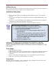
http://www.opengear.tv/dashboard-software/ Note that uploading firmware to the B264 does not affect its operation in any way and does not introduce any glitches in the inputs/outputs, except when running RTMP at high bit rate. If you are running RTMP at high bit rate, uploading firmware to the B264 may cause momentary stream interruptions.
Admin Config Files Tab As you make configuration changes to the B264, they are automatically persisted in non-volatile storage. If the card is rebooted or power-cycled, it will come back in the same configuration. In addition to automatic configuration persistency, the B264 also offers the ability to save up to 5 complete configurations, load them, and even export them.
Config Load Button: If you click on this button, the corresponding configuration is loaded in the B264 device. It will replace the currently-running configuration. Dashboard™ will take a few seconds to reload (longer if you are accessing over a widearea network), but the actual configuration in the B264 is virtually instantaneous. The Status Message Area will indicate the result of the operation.
copy configuration between openGear B264 and modular B264 encoders). This process is illustrated below: This process is discussed in further detail in the Dashboard User Manual, chapter 5, section Restoring Configurations to Devices. Pre-defined Templates The B264 offers 5 pre-defined configuration templates, as indicated below. To load a template, just click on the Load button next to it.
720p to Ethernet 1, 2 and ASI: This template configures both encoders to run from HD-SDI 720p inputs (Encoder 1 from Video 1, Encoder 2 from Video 2). Encoders are routed to individual multicasts on both Ethernet ports, and as an MPTS to both ASI Ports. 1080i to Ethernet 1, 2 and ASI: This template configures both encoders to run from HD-SDI 1080i inputs (Encoder 1 from Video 1, Encoder 2 from Video 2).
TPG Configuration Parameters Output Selection Connection Parameters The configuration interface is divided into two areas: TPG Configuration Parameters, described in this section. Output Selection Connection Parameters, described in the Destination Selection section of the Connections Tab chapter. The TPG Configuration Parameters are: Port Name: All B264 ports have a user-defined name, to facilitate routing. Enter any suitable name. Mode: controls the type of MPEG-2 transport packets generated.
Continuity Counter field. On request, Niagara Video can supply a test program for Windows or Linux that receives the Ramp48 packets and checks them. o PCR Packets: TPG is generating packets with a valid PCR field (stamped corresponding to the packet’s departure time at the configured bit rate). The packets have a small payload with random data, so the Continuity Counter field is valid and counting. PID: controls the PID of the generated packets.
OTT Protocols: OTT (Over-The-Top) Protocols are HTTP Live Streaming and RTMP. Licenses in this column are applicable to both protocols. Each instance of either protocol requires a license. OTT licenses are provided at no cost, please contact support@Niagara Video.com with your encoder serial number if you would like to enable these protocols. However, please note that RTMP only supports AAC-LC audio; the encoder must have AAC-LC licenses to run RTMP.
Admin Event Log Tab The B264 includes an Event Log in non-volatile storage. This event log can be used for faultfinding, and to check for error conditions. The following information is included in each B264 event in the log: Date: The calendar date in which the event occurred. Time: The time at which the event occurred. Severity: The severity of the event. The B264 defines three severity levels: o Error: These are events that affect the operation of the device.
If your frame controller has access to the Internet, you can point it to one of the public NTP servers for your region. You can find more details on this link: http://psp2.ntp.org/bin/view/Servers/WebHome For the B264, the NTP server IP address can be entered in the Control Tab. The full Admin Event Log tab is displayed below: The fields are: Log Download: The user interface only displays the last 10 events of each type.
Time Zone: To simplify the correlation of the events with your local time, you can set your time zone using this drop-down menu. Note that the B264 presents a simplified list, with standard GMT offsets. Note that standard GMT offsets do not change back and forth with Daylight Savings; you will need to make this adjustment manually if it is relevant to you. Current Time: This field indicates the B264 view of what the current date and time is.
Support Tab If you need support with your B264 encoder, you can contact Niagara Video Corporation by phone or e-mail: Phone number: +1 925-399-7201, Monday-Friday 9:00AM – 5:00PM Pacific Time E-mail: support@Niagara Video.com If you need to contact Technical Support, please be prepared to provide the following information: 1. A detailed description of the problem, and any actions taken to solve it. 2. A detailed description of the environment around the encoder.
Control Tab The Control Tab is used to configure the management Ethernet ports in the B264. This includes both the IP information, as well as the SNMP parameters. The Control Tab is only displayed for the B264. The B264 has two physical management (control) Ethernet ports. However, from a logical standpoint, they are a single port with a single IP address; the two connections are provided for control redundancy. If one port loses link, the unit can still be controlled from the other.
The configuration parameters are: Device Name: This field controls the top-level name of the device in the Dashboard tree. It defaults to “Standalone Encoder”. Changes to this field take effect immediately. IP Configuration: This field selects the control port IP configuration mode, as follows: o Static IP: This option selects a static IP configuration, specified by the IP Address, Subnet Mask, Default Gateway and DNS Server fields.
SNMP Configuration Tab The B264 includes a built-in SNMP agent with support for SNMP V1 and V2C. It will respond to SNMP transactions only on the control port, for security reasons. This tab includes the parameters for the SNMP configuration. Changes to these parameters take effect immediately.
The SNMP parameters are as follows: Read Community: this is the SNMP Read-Only community string. Write Community: this is the SNMP Read-Write community string. System Contact: this configures the value for the MIB-II System variable System Contact. Whatever value entered here is returned for SNMP queries to that variable. System Location: this configures the value for the MIB-II System variable System Location. Whatever value entered here is returned for SNMP queries to that variable.
Playing Video on a Web Page In general, there are two ways of playing video on a web page: Using a web-browser plugin or Using the HTML5
Firefox Safari Chrome Support Internet Explorer Support Web Pages Served by the B264 The B264 automatically generates web pages that will display the video being encoded, depending on the output mode of the encoder channels (please refer to the Encoder Connections Tab section). The pages will be available for the following output protocols: ASI/IP Streaming, as long as IP Outputs with multicast destination IP addresses have been defined. Direct HTTP Streaming.
Multicast Streaming If an encoder is connected to IP Output ports configured for multicast streaming (i.e., with a destination IP address in the range of 224.0.0.0 to 239.255.255.255), the B264 will generate a web page for that output in the relevant Ethernet port. Note that the video will only actually play if the network between the client and the encoder supports multicast.
If you configure an MPTS stream (i.e., both encoders routed to the same IP Output), the page will be available for both encoders, but the plugin will only play the first channel (Encoder 1). Also, the plugin will only play the first audio PID, even if secondary audio is configured.
If the IP address of the port being accessed is xxx.xxx.xxx.xxx, the available local HLS channels can also be accessed through this direct link: http://xxx.xxx.xxx.xxx/HLS/ The page accessed through this link will display a list of available local HLS channels, with the value configured for Program Name as the label: Note that HLS channels configured for remote servers will not be listed in this page, as the B264 has no way of knowing the actual link to these channels.
If the B264 is required to support clients on remote networks, make sure that a Default Gateway is entered in the corresponding Ethernet port configuration (see the Network Configuration Tab section). When replying to a request, the B264 will always use the Ethernet port where it received the request from.
port 8000. The reason for this requirement is that the plugin needs to know the listening port, and that value is passed to it by the automatically-generated pages from the B264. Niagara Video does not recommend connecting the Control Ports of the Modular B264 encoders directly to the Internet. There is insufficient protection on the openGear® and SNMP v2 protocols supported on that port. The Control Ports should only be connected to protected management networks.