
Operation Manual


13
B264 Indicators and Switches
The B264 card can be installed in the 10-slot DFR-8310 frame, or in the 20-slot DFR-8321 or
OG3-FR frames. Prior to installing the card, first install the corresponding rear panel I/O module.
Note that the rear I/O panel for the DFR-8321 and OG3-FR frames is different from the panel
for the DFR-8310; if you have the wrong panel, please contact Niagara Video to have it
replaced
1
.
Rear I/O Panel Indicators
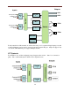
There are two rear I/O panels available for the B264 encoder, to support different analog audio
inputs:
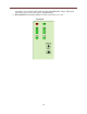
Unbalanced Audio I/O Panel
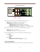
Balanced Audio I/O Panel
All B264 I/O panels have two software-configurable Composite/SDI video inputs on standard
BNC connectors, two ASI output ports on standard BNC connectors, and two 100/1000 Mb/s
Ethernet ports on standard RJ-45 connectors. The unbalanced audio I/O panel includes four
RCA connectors, and the balanced audio I/O panel includes four terminal blocks. The panels are
depicted in the next page.
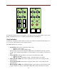
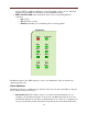
Each of the video inputs has a green indicator LED, with the following states:
LED off: no video signal detected, or input not configured.
LED flashing: video input locked to the video signal.
o LED flashing about once per second: input video is SD.
o LED flashing about twice per second: input video is HD-SDI.
o LED flashing about 4 times per second: input video is 3G-SDI (1080p60).
Each of the ASI output ports has a green indicator LED, with the following states:
LED off: ASI output port is disabled.
LED flashing: ASI output port is configured and enabled.
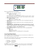
Each of the Gigabit Ethernet ports has two indicator LEDs, with the following states:
Green LED:
o Off: No link
o On: Link
Yellow LED:
o Off: No activity (transmit and/or receive)
o Flashing: Port is currently transmitting and/or receiving
1
The Balanced Audio I/O panel is not available for the 10-slot DFR-8310.