C-NPS-0720 AHEAD OF THE FLOW ® NIBCO Press System ®
Business-to-Business Solutions Look to NIBCO for technology leadership. The velocity with which e-business evolves demands that new products and services be continuously developed and introduced to keep our customers at the center of our business efforts. NIBCO provides an entire suite of business-to-business solutions that is changing the way we interact with customers. NIBCOpartner.
AHEAD OF THE F L O W® www.nibco.com Revised 7/24/2020 NIBCO® Press System Table of Contents Visit our website for the most current information. Page Contents.......................................................................................... 1 Fittings........................................................................................ 3-10 Applications Chart .................................................................... 4 Adapters......................................................
AHEAD OF THE F L O W® www.nibco.com Revised 11/9/2017 Quick and Easy The NIBCO Press System is user friendly, quick and easy to install. Installation can be completed in less time than traditional solder, threaded, brazed or grooved copper systems. Significant time savings means tight budgets and deadlines are met while project delays and cost overruns are avoided. Full System Product Offering The NIBCO Press System is more than just 1/2" to 4" fittings.
AHEAD OF THE F L O W® www.nibco.com Fittings Visit our website for the most current information. NIBCO INC. WORLD HEADQUARTERS • 1516 MIDDLEBURY ST. • ELKHART, IN 46516-4740 • USA • PH: 1.800.234.0227 TECH SERVICES PH: 1.888.446.4226 • FAX: 1.888.336.4226 • INTERNATIONAL OFFICE PH: +1.574.295.3327 • FAX: +1.574.295.3455 www.nibco.
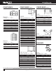
AHEAD OF THE www.nibco.com F L O W® Press Fitting Applications Chart Types of Service Comments Compatible with EPDM Seal Pressure Temperature 200 psi 32°F to 250°F • 200 psi -20°F to 250°F • 200 psi -20°F to 250°F 200 psi -20°F to 250°F Cooling Water 200 psi -20°F to 250°F Ethanol 200 psi -20°F to 250°F Less than 25mg/m3 Oil Content 200 psi Up to 140°F Keep Oil and Fat Free/Non-Liquid O2 140 psi Up to 140°F 200 psi Up to 140°F 200 psi Ambient 125 psi Up to 250°F Max 29.
AHEAD OF THE www.nibco.com F L O W® Revised 1/3/2020 ADAPTERS ADAPTERS NOM. SIZE 1/2 1/2 x 3/8 1/2 x 3/4 3/4 3/4 x 1/2 1 1 x 1/2 1 x 3/4 1 x 1 1/4 1 1/4 1 1/4 x 1 1 1/4 x 1 1/2 1 1/2 1 1/4 x 2 1 1/2 x 1 1/4 2 2 1/2 3 4 APPROX. NET WT./LBS. .103 .081 .151 .158 .153 .237 .172 .217 .436 .372 .359 .425 .518 .276 .515 .672 1.222 1.756 3.238 DIM.
AHEAD OF THE COUPLINGS 1/2 3/4 1 1 1/4 1 1/2 2 2 1/2 3 4 Reducing Coupling P x P – Wrot DIM. A INCHES .083 .157 .198 .271 .530 .691 .669 .979 2.134 / / 5/32 5/ 32 3/16 5/ 32 3 16 5 32 1/ 8 1/ 8 7/ 32 PC600-RS Coupling P x P – Wrot NOM. SIZE 2 1/2 3 4 .688 .979 2.134 DIM. A INCHES NOM.
AHEAD OF THE www.nibco.com F L O W® Revised 3/12/2020 ELBOWS (Cont.) PC606-2 45° Elbow Ftg x P – Wrot PC607-2 90° Elbow Ftg x P – Wrot NOM. SIZE APPROX. NET WT/LBS. DIM. B INCHES DIM. C INCHES 1/2 3/4 1 1 1/4 1 1/2 2 2 1/2 3 4 .094 .171 .248 .368 .673 1.057 1.050 1.526 3.284 15/16 113/32 117/32 13/4 25/16 25/8 23/16 219/32 33/32 7/16 17/32 9/16 11/16 13/16 1 29/ 32 15/32 117/32 1/2 3/4 3/4 x 1/2 1 1 x 3/4 1 1/4 1 1/2 2 2 1/2 3 4 APPROX. NET WT./LBS. .110 .223 .201 .331 .321 .528 .895 1.
AHEAD OF ELBOWS (Cont.) PC705-D Vent Elbow P x P – Forged Brass NOM. SIZE APPROX. NET WT. LBS. 1/2 3/4 .010 .010 DIMENSIONS INCHES D E C 19/32 19/32 9/16 3/4 3/4 11/16 PC605 Stiffener – Wrot NOM. SIZE APPROX. NET WT. LBS. 3/4 .043 PC707-3-5-LF 90° Drop Elbow P x F – Cast *Lead Free NOM. SIZE APPROX. NET WT. LBS. 1/2 3/4 .252 .588 www.nibco.
AHEAD OF THE www.nibco.com F L O W® Revised 2/28/2020 TEES PC611 Tee P x P x P – Wrot NOM.
AHEAD OF THE UNIONS ACCESSORIES (Cont.) PC634 Union P x P – Wrot 1/2 3/4 1 1 1/4 1 1/2 2 Revised 10/7/2019 UNIONS PC633 NOM. SIZE www.nibco.com F L O W® APPROX. NET WT./LBS. .383 .527 .804 1.107 1.703 2.368 DIM. A INCHES 15/16 19/32 111/32 119/32 121/32 127/32 EPDM Seal (leak detection for PC-FP600A-LF ONLY) Tailpiece P x F BSP NOM. SIZE APPROX. NET WT./LBS. 1/2 X 1 3/4 X 1 1X1 1 X 1 1/4 0.1840 0.2230 0.2320 0.3530 DIM.
AHEAD OF THE www.nibco.com F L O W® Valves Visit our website for the most current information. NIBCO INC. WORLD HEADQUARTERS • 1516 MIDDLEBURY ST. • ELKHART, IN 46516-4740 • USA • PH: 1.800.234.0227 TECH SERVICES PH: 1.888.446.4226 • FAX: 1.888.336.4226 • INTERNATIONAL OFFICE PH: +1.574.295.3327 • FAX: +1.574.295.3455 www.nibco.
AHEAD OF THE www.nibco.
AHEAD OF THE www.nibco.
AHEAD OF THE www.nibco.com F L O W® Revised 1/3/2020 NIBCO® 585HP Lead-Free Bronze Ball Valve Features: Silicon Performance Bronze® Alloy • Laser-Welded Cast Body • Triple-Sealed Stem • Reversible Handle • Easily Adjustable Packing Nut • Blowout-Proof Stem • Press Ends Leak Detection Approvals: MSS-SP110/145 • IAPMO/ANSI Z1157 • NSF/ANSI/CAN 61-8 Commercial Hot 180° F • NSF/ANSI 372 • ICC-ES PMG-1558 • ASME A112.4.14/CSA B125.
AHEAD OF THE www.nibco.com F L O W® Revised 1/3/2020 NIBCO® 585HP Lead-Free Bronze Ball Valve Features: Silicon Performance Bronze® Alloy • Laser-Welded Cast Body • Triple-Sealed Stem • Stainless Trim • Reversible Handle • Easily Adjustable Packing Nut • Blowout-Proof Stem • Press Ends Leak Detection Approvals: MSS-SP110/145 • IAPMO/ANSI Z1157 • NSF/ANSI/CAN 61-8 Commercial Hot 180° F • NSF/ANSI 372 • ICC-ES PMG-1558 • ASME A112.4.14/CSA B125.
AHEAD OF THE www.nibco.com F L O W® Revised 7/23/2020 NIBCO® 585HP Lead-Free Bronze Ball Valves Features: Silicon Performance Bronze® Alloy • Laser-Welded Cast Body • Triple-Sealed Stem • Reversible Handle • Easily Adjustable Packing Nut • Blowout-Proof Stem • Press Ends Leak Detection Approvals: MSS-SP110/145 • IAPMO/ANSI Z1157 • NSF/ANSI/CAN 61-8 Commercial Hot 180° F • NSF/ANSI 372 • ICC-ES PMG-1558 • ASME A112.4.14/CSA B125.
AHEAD OF THE www.nibco.
AHEAD OF THE www.nibco.com F L O W® Revised 7/25/2018 NIBCO® Press System Bronze Ball Valves Two-Piece Body • Full Port • Bronze Trim • Blowout-Proof Stem • Press Ends Leak Detection Dezincification Resistant 250 psi/17.2 bar non-shock cold working pressure 250°F maximum operating temperature CONFORMS TO MSS SP-110 MATERIAL LIST PART SPECIFICATION 1. Body 2. Body End 3. Press End Adapter (2) 4. Ball 5. Seat Ring (2) 6. Boss seal o-ring (2) 7. O-Ring (2) 8. Packing 9. Pack Gland 10.
AHEAD OF THE www.nibco.com F L O W® Revised 7/25/2018 NIBCO® Press System Bronze Ball Valves Two-Piece Body • Full Port • Stainless Trim • Blowout-Proof Stem • Vented Ball • Press Ends Leak Detection Dezincification Resistant 250 psi/17.2 bar non-shock cold working pressure 250°F maximum operating temperature CONFORMS TO MSS SP-110 MATERIAL LIST PART SPECIFICATION 1. Body 2. Body End 3. Press End Adapter (2) 4. Ball (vented) 5. Seat Ring (2) 6. Boss Seal O-Ring (2) 7. O-Ring (2) 8. Packing 9.
AHEAD OF THE www.nibco.com F L O W® Revised 7/25/2018 NIBCO® Press System Bronze Ball Valves Two-Piece Body • Full Port • Bronze Trim • Blowout-Proof Stem • Press Ends Leak Detection Dezincification Resistant 250 psi/17.2 bar non-shock cold working pressure 250°F maximum operating temperature CONFORMS TO MSS SP-110 MATERIAL LIST PART SPECIFICATION 1. Handle Nut 2. Stem 3. Pack Gland 4. Packing, Stem 5. Thrust Washer 6. Handle Assembly 7. Body End 8. Seat Ring (2) 9. Ball 10. Body 11.
AHEAD OF THE www.nibco.com F L O W® Revised 7/25/2018 NIBCO® Press System Bronze Ball Valves Dezincification Resistant Two-Piece Body • Full Port • Stainless Trim • Blowout-Proof Stem • Vented Ball • Press Ends Leak Detection 250 psi/17.2 bar non-shock cold working pressure 250°F maximum operating temperature CONFORMS TO MSS SP-110 MATERIAL LIST PART SPECIFICATION 1. Handle Nut 2. Stem 3. Pack Gland 4. Packing, Stem 5. Thrust Washer 6. Handle Assembly 7. Body End 8. Seat Ring (2) 9.
AHEAD OF THE www.nibco.com F L O W® Revised 10/15/2019 NIBCO® Press System Bronze Ball Valves Two-Piece Body • Full Port • Bronze Trim • Blowout-Proof Stem• 3/4" Hose Connection w/Cap and Chain • Press Ends Leak Detection 250 psi/17.2 bar non-shock cold working pressure 250°F maximum operating temperature CONFORMS TO MSS SP-110 MATERIAL LIST PART SPECIFICATION 1. Press End Adapter 2. Body 3. Hose Body End 4. Cap 5. O-Ring 6. Boss seal o-ring 7. Ball 8. Packing 9. Pack Gland 10. Stem 11.
AHEAD OF THE www.nibco.com F L O W® Revised 10/15/2019 NIBCO® Press System Bronze Ball Valves Two-Piece Body • Full Port • Stainless Trim • Blowout-Proof Stem • Vented Ball • 3/4" Hose Connection with Cap and Chain • Press Ends Leak Detection 250 psi/17.2 bar non-shock cold working pressure 250°F maximum operating temperature CONFORMS TO MSS SP-110 MATERIAL LIST PART SPECIFICATION 1. Press End Adapter 2. Body 3. Hose Body End 4. Cap 5. O-Ring 6. Boss seal o-ring 7. Ball (vented) 8. Packing 9.
AHEAD OF THE www.nibco.
AHEAD OF THE www.nibco.
AHEAD OF THE www.nibco.
AHEAD OF THE www.nibco.
AHEAD OF THE www.nibco.
AHEAD OF THE www.nibco.
AHEAD OF THE www.nibco.
AHEAD OF THE www.nibco.
AHEAD OF THE www.nibco.
AHEAD OF THE www.nibco.
AHEAD OF THE www.nibco.com F L O W® Revised 7/25/2018 NIBCO® Press System Lead-Free Brass Ball Valves Features: Press Ends Leak Detection • Two-Piece Body • PTFE Seats • Full Port • Blowout-Proof Stem Approvals: IAPMO/ANSI Z1157 (IGC-157) • NSF/ANSI-61 & 372 • MSS SP-145 • Conforms to ASME B16.
AHEAD OF www.nibco.com F L O W® THE Revised 7/25/2018 NIBCO® Press System Lead-Free Brass Ball Valves Features: Press Ends Leak Detection • Two-Piece Body • PTFE Seats • Full Port • Blowout-Proof Stem Approvals: IAPMO/ANSI Z1157 (IGC-157) • NSF/ANSI-61 & 372 • MSS SP-145 • Conforms to ASME B16.
AHEAD OF THE www.nibco.com F L O W® Revised 7/25/2018 NIBCO® Press System Lead-Free Brass Ball Valves Features: Press Ends Leak Detection • Wing Handle • Two-Piece Body • PTFE Seats • Full Port • Blowout-Proof Stem Approvals: IAPMO/ANSI Z1157 (IGC-157) • NSF/ANSI-61 & 372 • MSS SP-145 • Conforms to ASME B16.
AHEAD OF THE www.nibco.com F L O W® Revised 7/25/2018 NIBCO® Press System Lead-Free Brass Ball Valves Features: Press End Leak Detection • Two-Piece Body • PTFE Seats • Full Port • Blowout-Proof Stem Approvals: IAPMO/ANSI Z1157 (IGC-157) • NSF/ANSI-61 & 372 • MSS SP-145 • Conforms to ASME B16.
AHEAD OF THE www.nibco.com F L O W® Revised 7/25/2018 NIBCO® Press System Lead-Free Brass Ball Valves Features: Press End Leak Detection • Two-Piece Body • PTFE Seats • Full Port • Blowout-Proof Stem Approvals: IAPMO/ANSI Z1157 (IGC-157) • NSF/ANSI-61 & 372 • MSS SP-145 • Conforms to ASME B16.
AHEAD OF THE www.nibco.com F L O W® Revised 7/25/2018 NIBCO® Press System Lead-Free Brass Ball Valves Features: Press End Leak Detection • Side Drain/Bleeder • Two-Piece Body • PTFE Seats • Full Port • Blowout-Proof Stem Approvals: IAPMO/ANSI Z1157 (IGC-157) • NSF/ANSI-61 & 372 • MSS SP-145 • Conforms to ASME B16.
AHEAD OF THE www.nibco.com F L O W® Revised 7/25/2018 NIBCO® Press System Lead-Free Brass Ball Valves Features: Press End Leak Detection • 3/4" Hose Connection w/Cap • Two-Piece Body • PTFE Seats • Full Port • Blowout-Proof Stem Approvals: IAPMO/ANSI Z1157 (IGC-157) • NSF/ANSI-61 & 372 • MSS SP-145 • Conforms to ASME B16.
AHEAD OF THE www.nibco.com F L O W® Revised 6/26/2019 NIBCO® Press System Lead-Free Brass Ball Valves Features: Press End Leak Detection • PEX end F1960 Cold Expansion • Two-Piece Body • PTFE Seats • Blowout-Proof Stem • Double Stem Seal Approvals: MSS SP-110/145 • IAPMO/ANSI Z1157 • NSF/ANSI 14 61/372 • Conforms to ASME B16.
AHEAD OF THE www.nibco.com F L O W® Revised 6/26/2019 NIBCO® Press System Lead-Free Brass Ball Valves Features: Press End Leak Detection • PEX End F1807 Crimp • Two-Piece Body • PTFE Seats • Blowout-Proof Stem • Double Stem Seal Approvals: MSS SP-110/145 • IAPMO/ANSI Z1157 • NSF/ANSI 14 61/372 • Conforms to ASME B16.
AHEAD OF THE www.nibco.com F L O W® Revised 7/25/2018 NIBCO® Press System Lead-Free Brass Ball Valves Features: Press End Leak Detection • FIP Union • Two-Piece Body • PTFE Seats • Full Port • Blowout-Proof Stem Approvals: IAPMO/ANSI Z1157 (IGC-157) • NSF/ANSI-61 & 372 • MSS SP-145 • Conforms to ASME B16.
AHEAD OF THE www.nibco.com F L O W® Revised 6/26/2019 NIBCO® Press System Lead-Free Brass Ball Valves Features: Press Ends Leak Detection • Press x MIP Union • Two-Piece Body • PTFE Seats • Full Port • Blowout-Proof Stem Approvals: MSS SP-110/145 • IAPMO/ANSI Z1157 • NSF/ANSI 61/372 • Conforms to ASME B16.
AHEAD OF THE www.nibco.com F L O W® Revised 7/25/2018 NIBCO® Press System Lead-Free Brass Ball Valves Features: Press End Leak Detection • Solder Union • Two-Piece Body • PTFE Seats • Full Port • Blowout-Proof Stem Approvals: IAPMO/ANSI Z1157 (IGC-157) • NSF/ANSI-61 & 372 • MSS SP-145 • Conforms to ASME B16.
AHEAD OF THE www.nibco.com F L O W® Revised 6/26/2019 NIBCO® Press System Lead-Free Brass Ball Valves Features: Press End Leak Detection • Press x Press Union • Two-Piece Body • PTFE Seats • Full Port • Blowout-Proof Stem Approvals: MSS SP-110/145 • IAPMO/ANSI Z1157 • NSF/ANSI 61/372 • Conforms to ASME B16.
AHEAD OF www.nibco.com F L O W® THE Revised 6/26/2019 NIBCO® Press System Lead-Free Brass Ball Valves Features: Press Slip • Press Ends Leak Detection • Double Stem Seal • Two-Piece Body • PTFE Seats • Full Port • Blowout-Proof Stem Approvals: MSS SP-110/145 • IAPMO/ANSI Z1157 • NSF/ANSI 61/372 • Conforms to ASME B16.
AHEAD OF THE www.nibco.com F L O W® Revised 6/26/2019 NIBCO® Press System Lead-Free Brass Ball & Check Valves Features: All-in-one Ball and Inline Check Valve • Press Ends Leak Detection • Double Stem Seal • Two-Piece Body • PTFE Seats • Full Port • Blowout-Proof Stem Approvals: MSS SP-110/145 • IAPMO/ANSI Z1157 • NSF/ANSI 61/372 • Conforms to ASME B16.
AHEAD OF THE www.nibco.com F L O W® Revised 7/25/2018 NIBCO® Press System Bronze Gate Valves Dezincification Resistant Screw-In Bonnet • Rising Stem • Solid Wedge 200 psi/13.8 bar non-shock cold working pressure 250°F maximum operating temperature CONFORMS TO MSS SP-80 MATERIAL LIST PART SPECIFICATION 1. Handwheel Nut 2. Identification Plate 3. Handwheel 4. Stem 5. Pack Nut 6. Pack Gland 7. Packing 8. Bonnet 9. Body Assembly 10. Wedge 11. Female Adapter (2) 12.
AHEAD OF THE www.nibco.
AHEAD OF THE www.nibco.com F L O W® Revised 7/25/2018 NIBCO® Press System Bronze Gate Valves Dezincification Resistant Screw-In Bonnet • Non-Rising Stem • Solid Wedge 200 psi/13.8 bar non-shock cold working pressure 250°F maximum operating temperature CONFORMS TO MSS SP-80 MATERIAL LIST PART SPECIFICATION 1. Handwheel Nut 2. Identification Plate 3. Handwheel 4. Stem 5. Pack Nut 6. Pack Gland 7. Packing 8. Stuffing Box 9. Bonnet 10. Body Assembly 11. Wedge 12. Female Adapter (2) 13.
AHEAD OF THE www.nibco.
AHEAD OF THE www.nibco.com F L O W® Revised 7/25/2018 NIBCO® Press System Bronze Globe Valves Dezincification Resistant Screw-In Bonnet • Integral Seat • Renewable Seat and Disc 200 psi/13.8 bar non-shock cold working pressure 250°F maximum operating temperature PART 1. 2. 3. 4. 5. 6. 7. 8. 9. 10. 11. 12. 13. 14. 15. 16.
AHEAD OF THE F L O W® www.nibco.com Revised 7/25/2018 NIBCO® Press System Bronze Angle Valves Dezincification Resistant Screw-In Bonnet • Integral Seat • Renewable Seat and Disc 200 psi/13.8 bar non-shock cold working pressure 250°F maximum operating temperature CONFORMS TO MSS SP-80 MATERIAL LIST PART 1. 2. 3. 4. 5. 6. 7. 8. 9. 10. 11. 12. 13. 14. 15. 16.
AHEAD OF THE www.nibco.
AHEAD OF THE www.nibco.com F L O W® Revised 7/25/2018 NIBCO® Press System Bronze Check Valves Horizontal Swing • Regrinding Type • Y-Pattern • Renewable Seat and Disc 200 psi/13.8 bar non-shock cold working pressure 250°F maximum operating temperature PART Dezincification Resistant CONFORMS TO MSS SP-80 MATERIAL LIST 1. Bonnet 2. Body 3. Hinge Pin 4. Disc Hanger 5. Hanger Nut 6. Disc Holder 7. Seat Disc 8. Seat Disc Nut 9. Hinge Pin Plug *10. Seat Disc Washer 11. Female Adapter (2) 12.
AHEAD OF THE F L O W® www.nibco.com Revised 7/25/2018 NIBCO® Press System Bronze In-line Lift Check Valves In-Line Lift Type • Resilient Discs • Spring Actuated Dezincification Resistant 200 psi/17.2 bar non-shock cold working pressure 250°F maximum operating temperature MATERIAL LIST PART SPECIFICATION 1.
AHEAD OF THE www.nibco.com F L O W® Revised 7/25/2018 NIBCO® Press System Butterfly Valves Ductile Iron Body • Extended Neck • Geometric Drive Molded-In Seat Liner • Lug Style with Press x Press Female Ends 200 psi/13.8 bar non-shock cold working pressure 250°F maximum operating temperature CONFORMS TO MSS-SP67 • MSS-SP25 • API-609 • NSF/ANSI-8 COMMERCIAL HOT 180°F (INCLUDES ANNEX F AND G) AND NSF/ANSI-372 PFD-2000 MATERIAL LIST 1. 2. 3. 4. 5. 6. 7. 8. 9. 10. 11. 12. 13. 14. 15.
AHEAD OF THE www.nibco.com F L O W® Revised 7/25/2018 NIBCO® Press System Bronze Ball Valves Dezincification Resistant Two-Piece Body • Full Port • Bronze Trim • Blowout-Proof Stem 600 psi/41.4 bar non-shock cold working pressure 250°F maximum operating temperature CONFORMS TO MSS SP-110 MATERIAL LIST PART SPECIFICATION 1. Handle Nut 2. Handle Assembly 3. Pack Gland 4. Packing 5. Stem 6. Thrust Washer 7. Ball 8. Seat Ring (2) 9. Body 10. Body End Piece 11.
AHEAD OF THE www.nibco.com F L O W® Revised 7/25/2018 NIBCO® Press System Bronze Ball Valves Two-Piece Body • Full Port • Stainless Trim • Blowout-Proof Stem • Vented Ball 600 psi/41.4 bar non-shock cold working pressure 250°F maximum operating temperature Nominal sizes 1/2" through 1" are UL certified to NSF/ANSI 61 CONFORMS TO MSS SP-110 MATERIAL LIST 1. 2. 3. 4. 5. 6. 7. 8. 9. 10. 11.
AHEAD OF THE www.nibco.com F L O W® Revised 7/25/2018 NIBCO® Press System Bronze Ball Valves Two-Piece Body • Full Port • Bronze Trim • ³⁄₄" Hose Connection with Cap and Chain • Blowout-Proof Stem 600 psi/41.4 bar non-shock cold working pressure 250°F maximum operating temperature CONFORMS TO MSS SP-110 MATERIAL LIST PART 1. Handle Nut 2. Handle 3. Pack Gland 4. Packing 5. Thrust Washer 6. Stem 7. Ball 8. Seat Rings 9. Body Assembly 10. Hose Body End 11. Cap 12. Gasket 13. Chain 14.
AHEAD OF THE www.nibco.com F L O W® Revised 7/25/2018 Class 125 Bronze Y-Strainers Screw-In Cap • Tapped Cap with Blow-Off Plug or Solid Cap • 20 Mesh SS Screen or SS Perforated Screen 200 psi/13.8 bar non-shock cold working pressure 250° F maximum operating temperature CONFORMS TO MSS SP-110 MATERIAL LIST PART SPECIFICATION 1. Body 2. Cap 3. Gasket 4. Screen 5. Plug 6. Female Adapter (2) 7.
AHEAD OF THE www.nibco.com F L O W® Revised 11/9/2017 NIBCO® Press System Ball Valve Handle Options A wide variety of handles are available to fulfill safety and operation requirements in various processing and manufacturing industries. The lever handle with plastic cover is standard. Other handle options are shown. Stainless steel lever handles are available, as an option, also with plastic covers. If an optional handle is desired, please indicate which one when ordering.
AHEAD OF THE www.nibco.com F L O W® Revised 11/7/2017 NIBCO® Press System Bronze Ball Valves NIB-SEAL® Technical Data NIBCO bronze ball valves installed with NIB-SEAL insulated handles are the only approach that keeps your insulated piping system completely intact. The revolutionary NIB-SEAL bronze ball valve stops condensate cold. Its unique thermal barrier design keeps moisture from infiltrating your insulated system while preventing thermal energy loss through exposed metal handles.
AHEAD OF THE www.nibco.com F L O W® NIB-SEAL® Locking Handle U.S. PATENT 9,810,344 The patented technology of the 3-in-1 NIB-SEAL locking handle solves three problems at once: it extends, it insulates, and it locks. The innovative locking handle design extends valve actuation to provide ample room for insulating around piping systems, and its unique thermal barrier system prevents heat transfer and condensate development.
AHEAD OF www.nibco.com F L O W® THE Revised 8/7/2012 Butterfly Valve Options and Accessories Lever-Lock Operator (Standard) PFD2000 Position-Lock Operator (Optional) PFD2000 The lever-lock handle and throttling plate provide throttling notches every 10o for excellent manual control in balancing up to 90o or shut off service. The valve may be padlocked in any one of the positions including opened or closed by virtue of a locking hole located in the handle and lever.
AHEAD OF THE www.nibco.com F L O W® Revised 8/7/2012 Butterfly Valve Technical Information Valve Installation Procedure Always position the connecting pipe flanges accurately in the line, allowing sufficient space between the flanges for the valve. Make sure the pipe flange faces are clean of any foreign material such as scale, metal shavings or welding slag. Valves should be installed with the disc in the closed position to prevent damage to sealing surfaces. 1.
AHEAD OF THE F L O W® www.nibco.com Tools, Jaws & Chains Visit our website for the most current information. 68 NIBCO INC. WORLD HEADQUARTERS • 1516 MIDDLEBURY ST. • ELKHART, IN 46516-4740 • USA • PH: 1.800.234.0227 TECH SERVICES PH: 1.888.446.4226 • FAX: 1.888.336.4226 • INTERNATIONAL OFFICE PH: +1.574.295.3327 • FAX: +1.574.295.3455 www.nibco.
AHEAD OF THE www.nibco.com F L O W® Revised 7/25/2018 NIBCO® Press System Tools PC-280 1/2" through 4" PC-10S thru PC-15S Standard Pressing Jaws MATERIAL LIST MODEL NO. DESCRIPTION PC-280 Pressing Tool with 2 - 18V, 3.
AHEAD OF THE www.nibco.com F L O W® Revised 7/25/2018 NIBCO® Press System Tools PC-20M 1/2" through 1" MATERIAL LIST MODEL NO. DESCRIPTION LBS. PC-20M Mini Pressing Tool, 2 - 18V, 2.0 Ah Lithium-ion batteries, 110V charger & case (NO jaws) 10.10 PC-200M Mini Pressing Tool, 3 Jaws, 2 - 18V, 2.0 Ah Lithium-ion batteries, 110V charger & case 17.
AHEAD OF THE www.nibco.com F L O W® Revised 11/9/2017 NIBCO® Press System Tools PC-280 & PC-20M FEATURES PC-100 and PC-10M Accessories TOOLS MATERIAL LIST Light weight PC-20M Mini: 3.7 lbs. (without jaw) PC-280: 9.4 lbs. (without jaw) Easy to handle / simple design Jaws rotate 350° No calibration necessary No complicated switches or controls Mini: Ergonomic compact design is easy to use in tight spaces MODEL NO. DESCRIPTION LBS. PC-7 12V, NiMH Battery - 3.
AHEAD OF THE www.nibco.
AHEAD OF THE www.nibco.com F L O W® Engineering Data Visit our website for the most current information. NIBCO INC. WORLD HEADQUARTERS • 1516 MIDDLEBURY ST. • ELKHART, IN 46516-4740 • USA • PH: 1.800.234.0227 TECH SERVICES PH: 1.888.446.4226 • FAX: 1.888.336.4226 • INTERNATIONAL OFFICE PH: +1.574.295.3327 • FAX: +1.574.295.3455 www.nibco.
AHEAD OF THE www.nibco.com F L O W® Revised 9/17/2019 NIBCO® Press System — Engineering Data Copper and Copper Alloy Fittings Standards Performance O-ring seal joints are not new to the piping industry, but joining techniques like the NIBCO Press System are providing new alternatives for copper piping assembly. NIBCO has relied on its century of experience in copper and brass piping products to design the best performing and most dependable line of fittings possible.
AHEAD OF THE www.nibco.com F L O W® Revised 9/17/2019 NIBCO® Press System — Sample Specification FITTINGS 2" and Smaller: 21/2" through 4": Fittings shall comply with NSF 61, CSA, UPC and be approved by the local jurisdiction.
AHEAD OF THE www.nibco.com F L O W® Revised 11/9/2017 NIBCO® Press System — Sample Specification VALVES 2" and Smaller Ball Valves: (on/off, isolation or throttling) Ball valves with male or female press-to-connect ends shall be rated at 200 psi CWP to +250°F maximum. Valves shall be manufactured in accordance with MSS SP-110 and constructed of dezincification resistant cast bronze bodies. No brass containing more than 15% zinc shall be approved.
AHEAD OF THE F L O W® www.nibco.com Installation Instructions Visit our website for the most current information. NIBCO INC. WORLD HEADQUARTERS • 1516 MIDDLEBURY ST. • ELKHART, IN 46516-4740 • USA • PH: 1.800.234.0227 TECH SERVICES PH: 1.888.446.4226 • FAX: 1.888.336.4226 • INTERNATIONAL OFFICE PH: +1.574.295.3327 • FAX: +1.574.295.3455 www.nibco.
AHEAD OF THE www.nibco.com F L O W® Revised 9/17/2019 NIBCO® Press System — Installation Instructions NIBCO Press System The NIBCO Press System, when used with tested and authorized pressing tools and jaws, is designed to mechanically crimp fittings and valves onto copper tubing to create a watertight, permanent seal. When the switch on the pressing tool is depressed a small hydraulic pump generates thousands of pounds of crimping force to install the specially designed fittings and valves.
AHEAD OF THE www.nibco.com F L O W® Revised 11/9/2017 NIBCO® Press System — Installation Instructions Installation Instructions for 1/2" - 2" Press Fittings and Valves WARNING: To prevent serious injury, inspect the pressing tool, battery charger (if applicable) and jaw sets according to the procedure outlined in the pressing tool instruction manual prior to beginning installation. Failure to clean jaws can result in an improper connection that can lead to extensive property damage.
AHEAD OF THE www.nibco.com F L O W® Revised 11/9/2017 NIBCO® Press System — Installation Instructions 4. Select the jaw set that corresponds to the size of the joint to be crimped and insert the jaw set into the pressing tool (Figure 5). Figure 8 — Jaw set should be square to tubing Figure 5 — Inserting the NIBCO Press System jaw 5. Push the jaw set mounting pin until it clicks into position. NOTE: The tool will not properly press unless the pin is fully engaged.
AHEAD OF THE www.nibco.com F L O W® Revised 11/9/2017 NIBCO® Press System — Installation Instructions Installation Instructions for 2 1/2" - 4" Press Fittings and Valves WARNING: To prevent serious injury, the pressing tool, battery charger (if applicable) and pressing chains should be inspected according to the procedure outlined in the pressing tool instruction manual prior to beginning installation.
AHEAD OF THE www.nibco.com F L O W® Revised 11/9/2017 NIBCO® Press System — Installation Instructions Crimping a NIBCO Press System Fitting or Valve CAUTION: NIBCO press fittings and valves (2½”, 3”, 4” ends) to be installed ONLY with: • NIBCO PC-100 and PC-280 pressing tools • NIBCO PC-5 adapter jaw • NIBCO pressing chain - 2½” (PC-2), 3” (PC-3), 4” (PC-4) 1. Make sure that the battery is removed or that the cord is unplugged on the pressing tool prior to attaching or changing the adapter jaw. 2.
AHEAD OF THE F L O W® www.nibco.com Revised 2/28/2020 NIBCO® Press System — Crimp Integrity Testing Instructions for Fittings & Valves PRESSURE TESTING: NIBCO recommends the following leak testing procedures when installing NIBCO Press System with the leak detection feature. These test procedures allow the installer to find un-pressed connections while the system is being tested under pressure.
AHEAD OF THE www.nibco.com F L O W® Revised 9/17/2019 NIBCO® Press System — Installation Instructions Minimum Distance Between Joints Spacing To prevent distortion of the tubing, certain fitting sizes require a minimum distance between crimp joints (refer to Chart 1 below). Failure to provide this minimum distance may result in an improper seal. 1. Sufficient clearance must be left around each joint to allow room for the pressing tool and jaw to be attached without interference.
AHEAD OF THE www.nibco.com F L O W® Revised 9/17/2019 NIBCO® Press System — Frequently Asked Questions What is the NIBCO product offering? The NIBCO Press System features a full range of copper and copper alloy fittings, commercial valves, accessories and pressing tools, jaws and chains for use with K, L and M copper water tube as well as 1/2", 3/4" and 1" annealed copper tubing.
AHEAD OF THE F L O W® www.nibco.com Notes Visit our website for the most current information. 86 NIBCO INC. WORLD HEADQUARTERS • 1516 MIDDLEBURY ST. • ELKHART, IN 46516-4740 • USA • PH: 1.800.234.0227 TECH SERVICES PH: 1.888.446.4226 • FAX: 1.888.336.4226 • INTERNATIONAL OFFICE PH: +1.574.295.3327 • FAX: +1.574.295.3455 www.nibco.
AHEAD OF THE www.nibco.com F L O W® NIBCO® Press System Limited Warranty NIBCO INC. warrants: • NIBCO Press System fittings and flanges to be free from defects in materials and workmanship under normal use and service for a period of 50 years from the Warranty Commencement Date. The Warranty Commencement Date for NIBCO Press system fittings and flanges shall be the date upon which the fitting or flange is installed.
AHEAD OF THE www.nibco.com F L O W® Revised 11/9/2017 How to Order State quantity, figure number and size for each valve you wish to order. See individual valve catalog pages for specific or special product designations. HOW MANY TO ORDER NIBCO valves are decimal packed for your convenience in handling, shipping and stock-keeping. Number in master carton varies with item. POLICY ON RETURNS TO FACTORY NO NIBCO valves are to be returned without prior written agreement. Transportation must be prepaid.
globally connecting you at all levels It’s a new age of business, and a new way at NIBCO. From Elkhart, Indiana to Lodz, Poland, and points beyond, our company has integrated manufacturing, distribution, and networked communications to provide a seamless source of information and service, 24 hours a day, 7 days a week. But this integration hasn’t happened overnight. It’s been part of a longterm strategic process that has pushed us to reconsider every aspect World Headquarters of our business.
C-NPS-0720 VALVES Pressure-rated bronze, iron and alloy-iron gate, globe and check valves • Pressurerated bronze ball valves • Boiler specialty valves • Commercial and industrial butterfly valves • Lined butterfly valves • Circuit balancing valves and kits • Carbon and stainless steel ball valves • ANSI flanged steel ball valves • Lined ball valves • Pneumatic and electric actuators and controls • Grooved ball and butterfly valves • High performance butterfly valves • UL/FM fire protection valves • MSS sp