AHEAD OF THE F L O W® www.nibco.com Installation Instructions Visit our website for the most current information. 78 NIBCO INC. WORLD HEADQUARTERS • 1516 MIDDLEBURY ST. • ELKHART, IN 46516-4740 • USA • PH: 1.800.234.0227 TECH SERVICES PH: 1.888.446.4226 • FAX: 1.888.336.4226 • INTERNATIONAL OFFICE PH: +1.574.295.3327 • FAX: +1.574.295.3455 www.nibco.
AHEAD OF THE www.nibco.com F L O W® Revised 9/17/2019 NIBCO® Press System — Installation Instructions NIBCO Press System The NIBCO Press System, when used with tested and authorized pressing tools and jaws, is designed to mechanically crimp fittings and valves onto copper tubing to create a watertight, permanent seal. When the switch on the pressing tool is depressed a small hydraulic pump generates thousands of pounds of crimping force to install the specially designed fittings and valves.
AHEAD OF THE www.nibco.com F L O W® Revised 11/9/2017 NIBCO® Press System — Installation Instructions Installation Instructions for 1/2" - 2" Press Fittings and Valves WARNING: To prevent serious injury, inspect the pressing tool, battery charger (if applicable) and jaw sets according to the procedure outlined in the pressing tool instruction manual prior to beginning installation. Failure to clean jaws can result in an improper connection that can lead to extensive property damage.
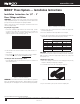
AHEAD OF THE www.nibco.com F L O W® Revised 11/9/2017 NIBCO® Press System — Installation Instructions 4. Select the jaw set that corresponds to the size of the joint to be crimped and insert the jaw set into the pressing tool (Figure 5). Figure 8 — Jaw set should be square to tubing Figure 5 — Inserting the NIBCO Press System jaw 5. Push the jaw set mounting pin until it clicks into position. NOTE: The tool will not properly press unless the pin is fully engaged.
AHEAD OF THE www.nibco.com F L O W® Revised 11/9/2017 NIBCO® Press System — Installation Instructions Installation Instructions for 2 1/2" - 4" Press Fittings and Valves WARNING: To prevent serious injury, the pressing tool, battery charger (if applicable) and pressing chains should be inspected according to the procedure outlined in the pressing tool instruction manual prior to beginning installation.
AHEAD OF THE www.nibco.com F L O W® Revised 11/9/2017 NIBCO® Press System — Installation Instructions Crimping a NIBCO Press System Fitting or Valve CAUTION: NIBCO press fittings and valves (2½”, 3”, 4” ends) to be installed ONLY with: • NIBCO PC-100 and PC-280 pressing tools • NIBCO PC-5 adapter jaw • NIBCO pressing chain - 2½” (PC-2), 3” (PC-3), 4” (PC-4) 1. Make sure that the battery is removed or that the cord is unplugged on the pressing tool prior to attaching or changing the adapter jaw. 2.
AHEAD OF THE F L O W® www.nibco.com Revised 2/28/2020 NIBCO® Press System — Crimp Integrity Testing Instructions for Fittings & Valves PRESSURE TESTING: NIBCO recommends the following leak testing procedures when installing NIBCO Press System with the leak detection feature. These test procedures allow the installer to find un-pressed connections while the system is being tested under pressure.
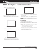
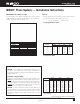
AHEAD OF THE www.nibco.com F L O W® Revised 9/17/2019 NIBCO® Press System — Installation Instructions Minimum Distance Between Joints Spacing To prevent distortion of the tubing, certain fitting sizes require a minimum distance between crimp joints (refer to Chart 1 below). Failure to provide this minimum distance may result in an improper seal. 1. Sufficient clearance must be left around each joint to allow room for the pressing tool and jaw to be attached without interference.