
Installation Guide

85
NIBCO INC. WORLD HEADQUARTERS • 1516 MIDDLEBURY ST. • ELKHART, IN 46516-4740 • USA • PH: 1.800.234.0227
TECH SERVICES PH: 1.888.446.4226 • FAX: 1.888.336.4226 • INTERNATIONAL OFFICE PH: +1.574.295.3327 • FAX: +1.574.295.3455
www.nibco.com
Visit our website for the most current information.
www.nibco.com
AHEAD OF THE FLOW
®
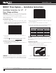
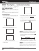
Minimum Distance Between Joints
To prevent distortion of the tubing, certain fitting sizes require a minimum
distance between crimp joints (refer to Chart 1 below). Failure to provide this
minimum distance may result in an improper seal.
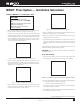
Spacing
1. Sufficient clearance must be left around each joint to allow room for the
pressing tool and jaw to be attached without interference.
Clearance Requirements — Standard Jaw Sets
NIBCO
®
Press System — Installation Instructions
Tube Dia.
Inches mm Inches mm
1
/2
15
/16 24 1
5
/8 41
3
/4
7
/8 22 2
1
/8 54
1 1
1
/4 31 2
1
/2 64
1
1
/4 1
1
/8 29 2
7
/8 73
1
1
/2 2 51 4
3
/8 111
2 2 51 4
3
/8 111
A (min.) B (min.)
Tube Dia.
Inches mm Inches mm Inches mm
1
/2 1
1
/8 28 1
3
/8 35 2
1
/2 64
3
/4 1 26 1
1
/2 38 2
1
/2 64
1 1
5
/16 34 1
3
/4 45 3 76
1
1
/4 1
1
/4 32 2
1
/4 57 3
1
/8 80
1
1
/2 2
1
/8 54 3
1
/8 80 5 127
2 2
1
/8 54 3
1
/8 80 5 127
2
1
/2 3
5
/8 92 6 152 3
1
/2 89
3 3
7
/8 98 6
1
/2 165 4 102
4 4
7
/8 124 7
5
/8 194 4
1
/4 108
A (min.) B (min.) C (min.)
System Support
CAUTION — In any installation, the system should be suported to ensure
the minimum stress is imposed on the tube and joints. The NIBCO Press
System should be supported in accordance with normal practice and to local
jurisdiction piping code.
Softening of Copper Tubing
A NIBCO Press System installation should not be conducted within 12" of a
brazed joint. The high temperature required for capillary joinery may cause
the copper tube to become annealed and render it too soft for proper crimp-
ing. However, a NIBCO Press System product may be crimped adjacent to a
soldered joint, as normal temperatures created by silver soldering are not
hot enough to cause the copper tube to become annealed.
CAUTION — Brazing or soldering should not be conducted within 12" of
an existing NIBCO Press System connection as this may damage the EPDM
seal. If there is any concern about heat damage to the O-ring, a cold, wet
cloth should be wrapped around the crimped connection prior to soldering
or brazing.
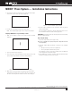
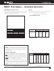
Tool perpendicular to wall
Tool angled to wall
NOTE: Clearance dimensions for 2
1
/2", 3" & 4" are for wrapping pressing
chains around fittings.
A (min.)
Tube Dia. Inches mm
1
⁄2"* 0 0
3
⁄4"* 0 0
1"* 0 0
1
1
⁄4"* 0 0
1
1
⁄2"* 0 0
2"* 0 0
2
1
⁄2"
3
⁄8" 10
3"
3
⁄8" 10
4"
3
⁄8" 10
*No minimum distance required.
Revised 9/17/2019