
User's Manual


GB
3
2.2) Connector and power supply cable (this section refers only to the NEOMAT MT version and concerns customer service
personnel only).
WARNING: if the power cord is damaged it must be replaced with an identical type supplied by the manufacturer or
an authorised customer service centre.
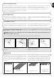
If it is necessary to disconnect the motor from the power supply cable proceed as shown in the figures below:
!
The NEOMAT series tubular motors are equipped with an electronic
limit switch system. The electronic control unit interrupts the move-
ment when the awning reaches the programmed open or closed
positions. These positions must be programmed into the memory
after the motor has been installed and the awning has been fully
mounted.
The motor can still be controlled even if these two positions, “0” (awning
closed) and “1” (awning open), have not yet been memorised; howev-
er, the movement in this case must be controlled manually. It is also
possible to program an intermediate position (Pos. “I”) for partial open-
ing of the awning. The “I” position and the activation of the torque
reduction function (RDC) can also be programmed at a later time.
Rotate the ring nut until the notch
matches one of the latch-on teeth,
then release.
Repeat the operation for the oth-
er tooth.
Bend the cable towards the inside
and remove the protection by rotat-
ing it gently towards the outside.
Pull out the connector.
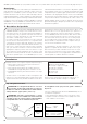
3) Adjustments
Awning fully closed
(Pos. “0”)
Intermediate position (“I”)
RDC torque reduction
start position in th
closing manoeuvre
Awning open (Pos.”1”)
2.1.2) “TTBUS” input:
The “TTBUS” has been designed to control the control units of
motors for awnings and rolling shutters. This Bus enables separate
control of up to 100 control units by connecting them in parallel
using only 2 conductors (Common and “TTBUS” wires). For further
information see the operating instructions for the remote controls via
“TTBUS”.
2.1.3) Weather sensors:
In the “Weather Sensor” input (between the Common wire and the
Weather sensor input) you can connect a simple wind sensor (ane-
mometer) or a special wind-sun-rain sensor. Up to 5 control units
can be connected in parallel to a single sensor. Be careful to obser-
ve the polarity of the signals (on all the motors, the black wire must
be connected with the black, the orange with the orange).
2.1.1) “Step-by-Step” Input:
To control the automation in manual mode it is possible to connect
a simple button (between the Common wire and the Step-by-Step
input). The operating mode follows this sequence: up-stop-down-
stop. If the button is held down for more than 3 seconds (but less
than 10), an UP movement is always activated (the one correspond-
ing to key ▲ on the radio controls).
If the button is held down for more than 10 seconds, a DOWN move-
ment is always activated (corresponding to key ▼).
This feature can be useful in order to “synchronise” multiple motors
to the same operation regardless of their current status.