
User's Manual


GB
3
2) Installation
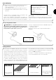
Proceed as follows to prepare the motor (fig. 4):
1. Position the ring gear (E) on the motor (A) until it fits into the
corresponding ring nut (F).
2. Mount the draw adapter (D) on the motor shaft.
3. On NEOMAT H, fasten the draw adapter with the snap ring.
Figure 4
A: NEOMAT H tubular motor
B: Fixing clips, cotter pins or screws
C: Support and spacer
D: Draw adapter
E: Ring gear
F: Ring nut
G: Rod for emergency manoeuvre
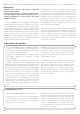
The NEOMAT H series tubular motors are equipped with an elec-
tronic limit switch system. The electronic control unit interrupts the
movement when the awning reaches the programmed open or
closed positions. These positions must be programmed into the
memory after the motor has been installed and the awning has been
fully mounted. The motor can still be controlled even if these two
positions, “0” (awning closed) and “1” (awning open), have not yet
been memorised; however, the movement in this case must be con-
trolled manually. It is also possible to program an intermediate posi-
tion (Pos. “I”) for partial opening of the awning.
If intermediate position “I” has been memorized, the awning can be
moved to the programmed position by pressing the 2 buttons ▼▲
on the transmitter simultaneously.
The “I” position and the activation of the torque reduction function
(RDC) can also be programmed at a later time.
3) Adjustments
Fit the assembled motor into the awning’s winding tube until it touch-
es the end of the ring gear (E).
Fasten the tube to the draw adapter (D) using the M4x10 screw in
order to prevent the motor from slipping or sliding axially (fig. 6).
Finally, secure the motor head to the special support (C) with the
clips, cotter pins or screws. (B).
A rod can be inserted in the head of the motor to enable movement
under emergency conditions (emergency manoeuvre).
2.1) Electrical connections
WARNING: For motor connections, an omnipolar dis-
connecting device with a 3-mm minimum distance
between contacts must be provided for disconnection
from the mains power supply (disconnecting switch or
plug and socket, etc.).
The cable used for the electrical connections of the NEOMAT H
motor has 3 wires:
• Phase, Neutral and Earth.
Make sure that the mains voltage corresponds to the ratings of
NEOMAT H.
!
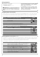
Awning fully closed
(Pos. “0”)
Intermediate position (“I”)
RDC torque reduction start
position in the closing
manoeuvre
Awning open (Pos.”1”)
Brown = Phase
Blue = Neutral
Yellow/Green = Earth