
Installation Instructions

5 – English
ELECTRICAL CONNECTIONS AND
FIRST POWER UP
3
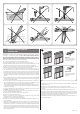
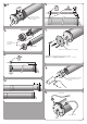
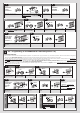
The motor has two separate cables: the power cable and the control cable. Each
cable has a connector for connection to the motor (fig. 3-h); the connectors are re-
movable and allow the possible replacement of cables (fig. 3-i). CAUTION! - The
smaller cables must be handled carefully because they contain very thin wires
that could be damaged.
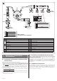
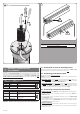
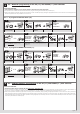
CABLE “A” is the POWER cable (fig. 2)
Wire Colour Connection
A1 Brown Power supply phase
OFF
A2 Blue Neutral
A3 Yellow-green Earth
CABLE “B” is the CONTROL cable (fig. 2)
Wire Colour Connection
B1 White
Voltage free contact for the Up com-
mand
OFF
B2 White-orange
Voltage free contact for the Down com-
mand / TTBus
B3 White-black Common
CAUTION! – DO NOT connect any wires from cable “B” to the power line.
3.1 - Connection of motor to electricity mains
The motor is powered by a permanent connection to the mains. Use cable “A” (fig.
2) for this connection, making sure to observe the warnings in full.
3.2 - Connecting push button panels
You can connect either 1 or 2 button panels.
Caution! - The maximum length of the cables used to connect a wall-mounted pan-
el or a relay is 100 m.
– Model with 1 button excites an input: the command is either Open (factory set-
ting) or Step-by-step; the command is memorised with procedure A.7. The panel
must be connected to the white and white-black wires.
– Model with 2 buttons excites two inputs: one for the Up command, and one for
the Down command; it is also possible to program the operating logic using pro-
cedure A.5. The Open and Close inputs are constrained to reach other, in other
words they must be used with the same push button panel (fig. 2).
3.3 - Connecting accessories and sensors
• Cabled accessories: use cable “B” referring to fig. 3 and the following instruc-
tions.
– You can connect only one compatible accessory at a time to the white and
white-black cables.
– You can connect only one compatible accessory at a time to the white-orange
and white-black cables.
– Up to 5 tubular motors can be connected to one accessory, respecting the polar-
ity of the signals (connect the white-black cables of all motors together as well as
the white-orange cables of all motors).
• Wireless accessories:
– These are either portable transmitters or climate sensors. For how to program/
memorise them, refer to the procedures given in this manual and in the device
manuals themselves.
l
1
3
2
i
3
CAUTION! - The smaller cables must be handled carefully because they
contain very thin wires that could be damaged.
For eventual extraction of the connector