
Installation Instructions
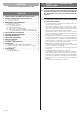
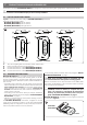
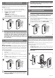

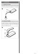

Table Of Contents

ENGLISH – 3
PRODUCT DESCRIPTION AND INTENDED USE
2
2 PRODUCT DESCRIPTION AND INTENDED USE
Transmitters of the series MYGOBD (MYGOBD/A) are designed to control automations (gates, garage doors, road barriers and similar).
a
CAUTION! – Any use other than that specied herein or in environmental conditions other than those stated in this
manual is to be considered improper and is strictly forbidden!
2.1 LIST OF CONSTITUENT PARTS
“Figure 1” shows the main parts making up MYGOBD (MYGOBD/A) transmitters.
The range consists of three models:
– MYGO2BD (MYGO2BD/A) with two buttons
– MYGO4BD (MYGO4BD/A) with four buttons
– MYGO8BD (MYGO8BD/A) with eight buttons.
A
A
B
C
A
A
B
D
5
1
2
3
4
6
7
8
A
A
B
E
F
MYGO2BD - MYGO2BD/A MYGO4BD - MYGO4BD/A MYGO8BD - MYGO8BD/A
1
A Two-colour signalling LED and automation status request button
B Hole for unlocking and removing the rear shell
C Control buttons area for models MYGO2BD (MYGO2BD/A)
D Control buttons area for models MYGO4BD (MYGO4BD/A)
E-F Control buttons area for models MYGO8BD (MYGO8BD/A)
2.2 TRANSMITTER FUNCTIONS
MYGOBD (MYGOBD/A) are compatible with receivers that adopt the
“O-Code” (“O-Code/A”) one-way radio encoding system or the “BD”
two-way encoding system. The latter system offers the exclusive ad
-
vanced functions of the “NiceOpera” system, besides additional func-
tions, such as:
– the sending of the conrmation, from the receiver to the transmitter,
that the transmitted command was received. After the transmission,
if the command was received, the transmitter vibrates and the
green LED lights up for 2 seconds. In case of “command NOT
received”, the transmitter LED, after a series of orange ashes, re
-
mains lit red for 2 seconds.
– the sending of the automation’s status (for example, whether the
gate is open or closed): refer to the paragraph “STATUS REQUEST
PROCEDURE” on page 5).
– indication of the automation’s anomaly status: ashing of the red
LED and intermittent vibration.
The MYGOBD (MYGOBD/A) transmitters, congured in two-way
mode, can be memorised on maximum 10 two-way receivers [OXIBD
(OXIBD/A)]. If they are congured in one-way mode, they can be mem
-
orised on any desired number of one-way receivers.
For the encoding switch procedure, refer to the paragraph “ENCOD-
ING SWITCH PROCEDURE” on page 5.
l
Each single encoding allows for exploiting only the
functions linked to that specic encoding system.
With the memorisation of two-way transmitters in the OXIBD (OXIB-
D/A) receiver, the identication code of the same receiver is automati-
cally memorised by the transmitter.
a
WARNING! – If the two-way transmitter in the OXIBD
(OXIBD/A) receiver is deleted, to complete the oper-
ation it is necessary to also delete the transmitter’s
memory. To perform this procedure, refer to the para-
graph “DELETION PROCEDURE” on page 5.
MYGOBD (MYGOBD/A) transmitters can be programmed with the
ProView device (Figure 2).
ProView
MYGOBD
MYGOBD/A
2