
Datasheet

CONDUCTIVE POLYMER ALUMINUM SOLID ELECTROLYTIC CAPACITORS
CVseries
Chip Type, High Voltage / Long Life
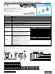
Specifications
Temperature Characteristics
(Max.Impedance Ratio)
Category Temperature Range
Rated Voltage Range
Rated Capacitance Range
Capacitance Tolerance
Tangent of loss angle (tan δ)
ESR
(1)
Leakage Current ( 2)
Performance CharacteristicsItem
–55 to +105°C
16 to 125V
5.6 to 680µF
±20% at 120Hz, 20°C
Less than or equal to the specified value
at
120Hz, 20°C
Less than or equal to the specified value
at
100kHz, 20°C
Less than or equal to the specified value . After 2 minutes' application of rated voltage at 20°C
Z+105°C / Z+20°C 1.25 (100kHz)
Z
–
55°C / Z+20°C 1.25
Endurance
Damp Heat
(Steady State)
Resistance to
Soldering Heat
Marking
The specifications listed at right shall be met when the
capacitors are restored to 20°C after the rated voltage is
applied for 3000 hours at 105°C.
The specifications listed at right shall be met when the
capacitors are restored to 20°C after the rated voltage is
applied for 1000 hours at 60°C, 90% RH.
After soldering the capacitor under the soldering conditions
prescribed here, the capacitor shall meet the specifications listed at
right, provided that it's temperature profile is measured at the
capacitor top and the terminal.
Pre-heating shall be done at 150 to 200°C and for 60 to 180 sec.
The duration for over +230°C temperature at capacitor surface shall
not exceed 60 seconds.
In the case of peak temp, less than 250°C, reflow soldering shall be
two times maximum.
In the case of peak temp, less than 260°C, reflow soldering shall be
once.
Measurement for solder temperature profile shall be made at the
capacitor top and the terminal.
Navy blue print on the case top
Capacitance change
tan δ
Leakage current ( 2)
ESR
(1)
Within ± 20% of the initial capacitance value ( 3)
150% or less than the initial specified value
150% or less than the initial specified value
Less than or equal to the initial specified value
Capacitance change
tan δ
Leakage current ( 2)
ESR
(1)
Within ± 20% of the initial capacitance value ( 3)
150% or less than the initial specified value
150% or less than the initial specified value
Less than or equal to the initial specified value
Capacitance change
tan δ
Leakage current ( 2)
ESR
(1)
Within ± 10% of the initial capacitance value ( 3)
130% or less than the initial specified value
130% or less than the initial specified value
Less than or equal to the initial specified value
High voltage (to 125V), Low ESR, High ripple current.
Load life of 3000 hours at 105°C.
SMD type : Lead free reflow soldering condition at
260°C peak correspondence.
Compliant to the RoHS directive (2002/95/EC).
1 ESR should be measured at both of the terminal ends closest where the terminals protrude through the plastic platform.
2 Conditioning : If any doubt arises, measure the leakage current after the voltage treatment of applying DC rated voltage continuously to the capacitor for 120
minutes at 105°C.
3 Initial value : The value before test of examination of resistance to soldering.
P
1
C
2
V
3
1
4
V
5
8
6
2
7
0
8
M
9
C
10
L
11
1
12
G
13
S
14
Configuration
Taping code
Size code
Capacitance toleranc (±20%)
Rated capacitance
(
82µF
)
Rated voltage
(
35V
)
Series name
Type
CV
82
V
012
H
0.3 MAX.
φD + 0.5 MAX.
B±0.2
A±0.2
C±0.2
0.5 MAX.
E
L
Series
Voltage
(V:35V)
Plastic platform
Lot No.
Capacitance
Negative
Positive
+0.1
-0.4
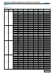
Dimensions
Type numbering system (Example : 35V 82µF)
Dimension table in next page.
CV
High Temperature
φD
L
A
B
C
E
H
6.3
5.9
7.3
6.6
6.6
2.1
0.5 to 0.8
Size
φ6.3
×
6L
8.0
6.9
9.0
8.3
8.3
3.2
0.8 to 1.1
φ8
×
7L
8.0
9.9
9.0
8.3
8.3
3.2
0.8 to 1.1
φ8
×
10L
8.0
11.9
9.0
8.3
8.3
3.2
0.8 to 1.1
φ8
×
12L
10.0
7.9
11.0
10.3
10.3
4.6
0.8 to 1.1
φ10
×
8L
10.0
9.9
11.0
10.3
10.3
4.6
0.8 to 1.1
φ10
×
10L
10.0
12.6
11.0
10.3
10.3
4.6
0.8 to 1.1
φ10
×
12.7L
(mm)
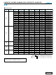
Code C
V 16
D
20
E
25
V
35
H
50
J
63
K
80
2A
100
2B
125
Voltage
CX
CAT.8100B