
Datasheet

ALUMINUM ELECTROLYTIC CAPACITORS
U
1
B
2
X
3
1
4
A
5
3
6
3
7
2
8
M
9
H
10
L
11
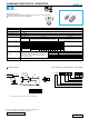
Configuration
Capacitance tolerance (±20%)
Rated capacitance (3300µF)
Rated voltage (10V)
Series name
Type
φD
10
Code
PL
12.5 to 18 HL
φD
P
φd
10
5.0
0.6
12.5
5.0
0.6
16
7.5
0.8
18
7.5
0.8
15
MIN
4
MIN
φD
+
0.5 MAX.
nichicon
3300
BX
10V
H1001
Rated Capacitance
Trade mark
Series
Laminated case
Rated Voltage
Lot No.
Pressure
relief vent
φd
L
+
1.5MAX.
(mm)
P
±0.5
BXseries
High Temperature Range, For +150°C Use
Laminated case series.
Suited for automobile electronics where heavy duty services are indispensable.
Compliant to the RoHS directive (2002/95/EC).
Radial Lead Type
Type numbering system (Example : 10V 3300
µ
F)
BX
BW
Dimension table in next page.
High
Temperature
Please refer to page 20, 21, 22 about the formed or taped product spec.
Please refer to page 4 for the minimum order quantity.
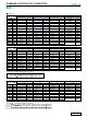
Item
Performance Characteristics
Category Temperature Range
Rated Voltage Range
Rated Capacitance Range
Capacitance Tolerance
Leakage Current
Tangent of loss angle (tan δ)
Stability at Low Temperature
Endurance
Marking
–55 to +150°C (10 to 100V), –40 to +150°C (160
·
200V), –25 to +150°C (350
·
400V)
10 to 400V
1 to 4700µF
±20% at 120Hz, 20°C
Black print on the case top.
Capacitance change
Leakage current
The specifications listed at right shall be met when the
capacitors are restored to 20°C after D.C. bias plus rated
ripple current is applied for 2000 hours (1000 hours for
φD=10 and 12.5) at 150°C, the peak voltage shall not
exceed the rated voltage.
Dissipation Factor
Within ±30% of the initial capacitance value (10 to 100V)
Within ±20% of the initial capacitance value (160 to 400V)
300% or less than the initial specified value (10 to 100V)
200% or less than the initial specified value(160 to 400V)
Less than or equal to the initial specified value
120Hz
Z–25°C / Z+20°C
Z–40°C / Z+20°C
Rated voltage (V)
120Hz 20°C
For capacitance of more than 1000µF, add 0.02 for every increase of 1000µF.
Rated voltage (V)
tan δ (MAX.)
10
0.20
16
0.16
25
0.14
35
0.12
50
0.10
63
0.10
80
0.08
100
0.08
160
·
200
0.20
350
·
400
0.24
Impedance ratio
ZT / Z20 (MAX.)
10
3
4
16
2
4
25
2
4
35
2
4
50
2
4
63
2
4
80
2
4
100
2
4
160
·
200
3
6
350
·
400
6
-
Rated Voltage (V)
Leakage current
After 1 minute's application of rated voltage, leakage current
is not more than 0.03CV or 4 (µA), whichever is greater.
160 to 400
CV
<
=
1000 :
I
=
0.1CV
+
40 (µA) max. (1 minute's)
CV
>
1000 :
I
=
0.04CV
+
100 (µA) max. (1 minute's)
10 to 100
• Please refer to page 20 about the end seal configulation.
CAT.8100A