
Datasheet


Performance Characteristics
Item
Rated voltage (V
)
15
MIN
4
MIN
φd
U
1
P
2
W
3
1
4
A
5
6
6
8
7
1
8
M
9
P
10
D
11 12
Configuration
Size code
Capacitance tolerance (±20%)
Rated capacitance (680µF)
Rated voltage (10V)
Series name
Type
Pressure relief vent
φ6.3up (No pressure relief vent for 7mmL products)
L
+
MAX.
P
±0.5
φD
+
MAX.
Sleeve
(
P.E.T.
)
φ D
Pb-free leadwire
Pb-free PET sleeve
4 · 5 DD
6.3 ED (7mm L : DD)
8 · 10 PD
12.5 to 18
HD
Configuration
20 to 25
RD
φD
P
φd
4
1.5
0.45
5
2.0
0.5
6.3
2.5
0.5
8
3.5
0.6
10
5.0
0.6
12.5
5.0
0.6
16
7.5
0.8
18
7.5
0.8
(0.45) (0.45)
0.8
(L = 7) 1.0
(L < 20) 1.5
(
L 20
)
2.0
: Applied to L>25 products
( ): Applied to 7mmL products
20
22
10.0 10.0
1.0 1.0
25
12.5
1.0
0.5
0.5
0.5 0.5 0.5 0.5
0.5 0.5
0.5
1.0 1.0
(mm)
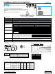
PWseries
Miniature Sized, Low lmpedance,
High Reliability For Switching Power Supplies
Radial Lead Type
Type numbering system (Example : 10V 680µF)
Smaller case size and lower impedance than PM series.
Low impedance and high reliability withstanding 2000 hours to 8000 hours.
Capacitance ranges available based on the numerical values in E12 series
under JIS.
Compliant to the RoHS directive (2002/95/EC).
Dimension table in next page.
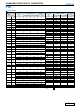
Specifications
Category Temperature Range
Rated
Voltage Range
Rated
Capacitance Range
Capacitance Tolerance
Leakage Current
Tangent of loss angle (tan
δ)
Stability at Low Temperature
Endurance
Shelf Life
Marking
–55 to +105˚C (6.3 to 100V), –40 to + 105˚C (160 to 400V), –25 to +105˚C (450V)
6.3 to 450V
0.47 to 15000µF
±20% at 120Hz, 20˚C
Printed with white color letter on dark brown sleeve.
After storing the capacitors under no load at 105˚C for 1000 hours and then performing voltage treatment based on JIS C 5101-4
clause 4.1 at 20°C, they shall meet the specified values for the endurance characteristics listed above.
Rated voltage (V)
6.3 to 100 160 to 450
Leakage current
After 1 minute's application of rated voltage, leakage current
is not more than 0.03CV or 4 (µA), whichever is greater.
CV
<
=
1000:
I =
0.1CV+40 (µA) max. (1 minute's)
CV > 1000:
I =
0.04CV+100 (µA) max. (1 minute's)
tan
δ
(
MAX.
)
6.3
0.22
10
0.19
16
0.16
25
0.14
35
0.12
50
0.10
63
0.09
100
0.08
160 to 250
0.15
315 · 350
0.20
400 · 450
0.25
For capacitance of more than 1000µ
F
, add 0.02 for every increase of 1000µ
F
. Measurement frequency : 120Hz, Temperature : 20˚C
120Hz
Z
–
25˚C / Z+20˚C
Rated voltage (V)
Impedance ratio
(MAX.)
6.3 · 10
—
—
3
16 · 25
—
—
3
35 · 50
—
—
3
63 · 100
—
—
3
160 · 200
3
4
—
250
3
6
—
315 · 350
4
8
—
400
6
10
—
450
15
—
—
Z
–
40˚C / Z+20˚C
Z
–
55˚C / Z+20˚C
The specifications listed at right shall be met when the
capacitors are restored to 20
˚
C after D.C. bias plus rated
ripple current is applied for 8000 hours (2000 hours for φD=4,
5 and 6.3, 3000 hours for φD=8, 5000 hours for φD=10, 7000
hours for φD=12.5) at 105
˚
C, the peak voltage shall not
exceed the rated voltage.
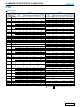
Frequency coefficient of rated ripple current
V
6.3 to 100
160 to 450
Frequency
Cap. (µF)
0.47 to 56000
68 to 330.
390 to 1000.
.1200 to 150000
0.47 to 22000
330 to 4700.
50Hz
0.20
0.55
0.70
0.80
0.80
0.90
120Hz
0.30
0.65
0.75
0.85
1.00
1.00
300Hz
0.50
0.75
0.80
0.90
1.25
1.10
1kHz
0.80
0.85
0.90
0.95
1.40
1.13
10kHz or more
1.00
1.00
1.00
1.00
1.60
1.15
Leakage current
tan
δ
Capacitance change
Less than or equal to the initial specified value
200% or less than the initial specified value
Within
±
20% of the initial capacitance value
PW
PM
Smaller
ALUMINUM ELECTROLYTIC CAPACITORS
Please refer to page 20, 21, 22 about the formed or taped product spec.
Please refer to page 4 for the minimum order quantity.
Low
Impedance
PA TT
• Please refer to page 20 about the end seal configulation.
Long Life
CAT.8100A