
Datasheet

U
1
U
2
J
3
1
4
H
5
3
6
3
7
1
8
M
9
N
10
QMS
11
1
12 13 14
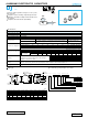
Configuration
Package code
Taping
Tray
MS
ZD
Capacitance Tolerance
(
±20%
)
Rated capacitance
(
330µF
)
Rated voltage
(
50V
)
Series name
Type
Size code
φD
12.5 to 18
20
Code
NQ
RQ
Type numbering system (Example : 50V 330
µ
F)
ALUMINUM ELECTROLYTIC CAPACITORS
UJseries
Chip Type, Higher Capacitance Range
Chip Type, higher capacitance in larger case sizes (φ12.5,
φ16, φ18, φ20)
Designed for surface mounting on high density PC board.
Applicable to automatic mounting machine fed with carrier
tape and tray.
Compliant to the RoHS directive (2002/95/EC).
UJ
UN
Bi-Polarized
UH
High
Temperature
Chip Type
H
A± 0.2 A±0.2
0.5 MAX.
E
Negative
Positive
nichicon
330 µF
UJ
50V
H1015
C± 0.2
B ± 0.2
Trade mark
Voltage
Series
Capacitance
Lot No.
12.5×13.5
4.8
13.6
13.6
4.0
13.5
1.0 to 1.4
φD
A
B
C
E
L
H
12.5
×16.
4.8
13.6
13.6
4.0
16.0
1.0 to 1.4
12.5
×21.
4.8
13.6
13.6
4.0
21.0
1.0 to 1.4
16×16.5.
5.4
17.1
17.1
6.3
16.5
1.0 to 1.4
16×21.5.
5.4
17.1
17.1
6.3
21.5
1.0 to 1.4
18×16.5.
6.4
19.1
19.1
6.3
16.5
1.0 to 1.4
18×21.5.
6.4
19.1
19.1
6.3
21.5
1.0 to 1.4
20×16.5.
6.2
21.1
21.1
8.8
16.5
1.3 to 1.7
20×21.5.
6.2
21.1
21.1
8.8
21.5
1.3 to 1.7
(mm)
0.3 MAX.
φD ± 0.5
L± 1.0
B ± 0.2
Plastic platform
Pressure
relief vent
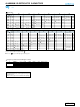
Endurance
Tangent of loss angle (tan δ)
Stability at Low Temperature
Item
The specifications listed at right shall be met when the
capacitors are restored to 20
°C
after the rated voltage is
applied for 5000 hours at 105
°C.
For capacitance of more than 1000µF, add 0.02 for every increase of 1000µF.
–55 to +105°C (6.3 to 100V), –40 to +105°C (160 to 450V)
6.3 to 450V
3.3 to 6800
µ
F
±20% at 120Hz, 20°C
Rated voltage (V)
After storing the capacitors under no load at 105°C for 1000 hours and then performing voltage treatment based on JIS C 5101-4
clause 4.1 at 20°C, they shall meet the specified values for the
endurance
characteristics listed above.
Black print on the case top.
6.3 to 100 160 to 450
After 1 minute's application of rated voltage, leakage current is not more
than 0.03CV or 4 (µA), whichever is greater.
I = 0.04CV+100 (µA) max.
(1 minute's)
—
Category
Temperature Range
Rated
Voltage Range
Rated
Capacitance Range
Capacitance Tolerance
Leakage Current
Shelf Life
Marking
Performance Characteristics
Specifications
Within
±20%
of the initial capacitance value
200% or less than the initial specified value
Less than or equal to the initial specified value
Capacitance change
Leakage current
tan δ
Rated voltage (V)
tan δ (MAX.)
Measurement frequency : 120Hz at 20°C
6.3
0.26
10
0.22
16
0.18
25
0.16
35
0.14
50
0.12
63
0.10
100
0.08
160 to 250
0.15
400
•
450
0.20
Z–25°C / Z+20°C
Z–40°C / Z+20°C
Rated voltage (V)
Impedance ratio
ZT / Z20 (MAX.)
Measurement frequency: 120Hz
6.3
5
10
10
4
8
16
3
6
25
2
4
35
2
3
50
2
3
63
2
3
100
2
3
160 to 250
3
6
400
•
450
6
10
Dimension table in next page.
CAT.8100B