
Datasheet


φD
P
φd
5
2.0
0.5
6.3
2.5
0.5
8
3.5
0.6
10
5.0
0.6
12.5
5.0
0.6
16
7.5
0.8
18
7.5
0.8
20
22
10.0 10.0
1.0 1.0
U
1
V
2
Y
3
1
4
A
5
3
6
3
7
1
8
M
9
E
10
D
11
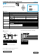
Configuration
Capacitance tolerance
(±20%)
Rated capacitance (330µF)
Rated voltage (10V)
Series name
Type
25
12.5
1.0
0.5 0.5 0.5 0.5 0.5 0.5 0.5 0.5 1.0 1.0
(L < 20) 1.5
(L 20) 2.0
φ D
5
Pb-free leadwire
Pb-free PET sleeve
DD
6.3 ED
8 · 10 PD
HD
Configuration
RD
12.5
to
18
20 to 25
Pressure
relief vent
15
MIN
4
MIN
φd
φD
+
MAX
P
±0.5
(φ6.3up)
L
+
MAX
Sleeve
(
P.E.T.
)
(mm)
VY
VZ
VK
ALUMINUM ELECTROLYTIC CAPACITORS
VYseries
Wide Temperature Range
One rank smaller case sizes than VZ series.
Compliant to the RoHS directive (2002/95/EC).
Radial Lead Type
Specifications
Type numbering system (Example : 10V 330µF)
Category
Temperature Range
Rated
Voltage Range
Rated
Capacitance Range
Capacitance Tolerance
Leakage Current
Tangent of loss angle (tan δ)
Stability at Low Temperature
Endurance
Shelf Life
Marking
Performance CharacteristicsItem
– 55 to +105˚C (6.3 to 100V), – 40 to +105˚C (160 to 400V), – 25 to +105˚C (450V)
6.3 to 450V
0.1 to 68000µF
±20% at 120Hz, 20˚C
Printed with white color letter on black sleeve.
After storing the capacitors under no load at 105˚C for 1000 hours and then performing voltage treatment based on JIS C 5101-4
clause 4.1 at 20°C, they shall meet the specified values for the endurance characteristics listed above.
Rated voltage (V
)
6.3 to 100 160 to 450
After 1 minute's application of rated voltage, leakage current
is not more than 0.03CV or 4 (µA), whichever is greater.
After 2 minutes' application of rated voltage, leakage current
is not more than 0.01CV or 3 (µA), whichever is greater.
After 1 minute's application of rated voltage,
CV
<
=
1000:
I
=
0.1CV+40 (µA) or less
After 1 minute's application of rated voltage,
CV
>
1000:
I
=
0.04CV+100 (µA) or less
Measurement frequency : 120Hz
The specifications listed at right shall be met when
the capacitors are restored to 20
°C
after the rated
voltage is applied for 1000 hours at 105
°C.
Rated voltage
(
V
)
tan
δ (
MAX.
)
6.3
0.28
10
0.24
16
0.20
25
0.16
35
0.14
50
0.12
63
0.10
100
0.08
160 to 250
0.20
350 to 450
0.25
For capacitance of more than 1000µ
F
, add 0.02 for every increase of 1000µ
F
. Measurement frequency : 120Hz, Temperature : 20˚C
Leakage current
tan
δ
Capacitance change
Less than or equal to the initial specified value
200% or less than the initial specified value
Within ±20% of the initial capacitance value
Please refer to page 20, 21, 22 about the formed or taped product spec.
Please refer to page 4 for the minimum order quantity.
• Please refer to page 20 about the end seal configulation.
Smaller
High
Temperature
Dimension table in next page.
Z–25˚C / Z
+
20˚C
Z–40˚C / Z
+
20˚C
Rated voltage
(
V)
Impedance ratio
ZT / Z20 (MAX.)
450
15
6.3
5
10
10
4
8
16
3
6
25
2
4
35 to 50
2
3
63 to 100
2
3
250 to 350
4
8
400
6
10
160 to 200
3
4
CAT.8100A