
Datasheet

ALUMINUM ELECTROLYTIC CAPACITORS
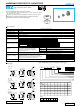
Series
Series
Voltage (C:16V)
Capacitance
(φ4 to φ6.3 )
(φ8 × 6.2 )
A2
33C
WZ
Plastic platform
0.3 MAX.
L
(L±0.3)
+0.1
–0.2
φD±0.5
B±0.2
C±0.2
0.5 MAX.
A±0.2 A±0.2
E
H
H
Positive
Negative
Trade mark
Lot No.
A2
220j
WZ
Plastic platform
0.3 MAX.
L±0.3
1 Apply to φ6.3 × 5.8, φ6.3 × 7.7
φD±0.5
B±0.2
C±0.2
0.5 MAX.
A±0.2 A±0.2
E
Positive
Negative
Voltage ( J:6.3V)
Capacitance
Lot No.
Series
(φ8 × 10, φ10×10)
H
Trade mark
A2
220E
WZ
Plastic platform
0.3 MAX.
L±0.5
φD±0.5
B±0.2
C±0.2
0.5 MAX.
A±0.2 A±0.2
E
Positive
Negative
Voltage (E:25V)
Capacitance
Lot No.
1
φD
4 to 6.3 (5.4L)
6.3 to 10 (L 5.8L)
code
GB
GS
A
B
C
E
L
H
4 × 5.4
1.8
4.3
4.3
1.0
5.4
0.5 to 0.8
5 × 5.4
2.1
5.3
5.3
1.3
5.4
0.5 to 0.8
6.3 × 5.4
2.4
6.6
6.6
2.2
5.4
0.5 to 0.8
6.3 × 5.8
2.4
6.6
6.6
2.2
5.4
0.5 to 0.8
6.3 × 7.7
2.4
6.6
6.6
2.2
7.7
0.5 to 0.8
8 × 6.2
3.3
8.3
8.3
2.3
6.2
0.5 to 0.8
8 × 10
2.9
8.3
8.3
3.1
10
0.8 to 1.1
10 × 10
3.2
10.3
10.3
4.5
10
0.8 to 1.1
φD
×
L
(mm)
U
1
W
2
Z
3
0
4
J
5
3
6
3
7
0
8
M
9
C
10
L
11
1
12
G
13
B
14
Configuration
Package code
Capacitance tolerance (±20%)
Rated capacitance (33µF)
Rated voltage (6.3V)
Series name
Type
WZseries
Corresponding with 260
°C peak reflow soldering
Recomended reflow condition : 260°C peak 5 sec 230°C over 60 sec 2 times
(
φ
8
×
6.2,
φ
10
×
10 : 1 time)
Chip type operating over wide temperature range of to –55 to +105
°C
.
Applicable to automatic mounting machine fed with carrier tape.
Compliant to the RoHS directive (2002/95/EC).
Chip Type
Type numbering system (Example : 6.3V 33
µ
F)
Specifications
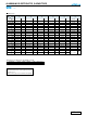
Category
Temperature Range
Rated
Voltage Range
Rated
Capacitance Range
Capacitance Tolerance
Leakage Current
Tangent of loss angle (tan δ)
Stability at Low Temperature
Endurance
Shelf Life
Marking
Performance CharacteristicsItem
–55 to +105°C
6.3 to 50V
0.1 to 1500µF
±20% at 120Hz, 20°C
After 2 minutes' application of rated voltage, leakage current is not more than 0.01CV or 3 (µA) , whichever is greater.
Black print on the case top.
Measurement frequency : 120Hz at 20°C
Measurement frequency : 120Hz
The specifications listed at right shall be
met when the capacitors are restored to
20°C after the rated voltage is applied for
1000 hours at 105°C.
After storing the capacitors under no load at 105°C for 1000 hours and then performing voltage treatment based on JIS C 5101-4
clause 4.1 at 20°C, they shall meet the specified values for the
endurance
characteristics listed above.
Resistance to soldering
heat
The capacitors are kept on a hot plate for 30 seconds, which is
maintained at 250°C. The capacitors shall meet the
characteristic requirements listed at right when they are
removed from the plate and restored to 20°C.
Rated voltage (V)
tan δ (MAX.)
6.3
0.30
10
0.24
16
0.20
25
0.16
35
0.14
50
0.14
Z–25°C / Z+20°C
Z–40°C / Z+20°C
Rated voltage (V)
Impedance ratio
ZT / Z20 (MAX.)
6.3
4
8
10
3
8
16
2
4
25
2
4
35
2
3
50
2
3
Capacitance
change
Leakage current
tan δ
Within ±25% of the initial capacitance value for capacitors of 16V or less.
Within ±20% of the initial capacitance value for capacitors of 25V or more.
200% or less than the initial specified value
Less than or equal to the initial specified value
Capacitance change
Leakage current
tan δ
Within ±10% of the initial capacitance value
Less than or equal to the initial specified value
Less than or equal to the initial specified value
Dimension table in next page.
WZ
Voltage
V 6.3 10 16 25 35 50
Code j A C E V H
Chip Type, Wide Temperature Range
High Temperature (260
°C) Reflow
WT
High
Temperature
Reflow
CAT.8100B