Section 2 Installation Contents: 2.1 Operating environment 2.2 Preliminary operations 2.3 Telemarketing socket connections 2.4 RS232, RS488 and AGC socket connections 2.
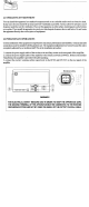
.1 OPERATING ENVIRONMENT You can install the apparatus in a standard component rack or on a suitable surface such as a bench or desk. In any case, the area should be as clean and well-ventilated as possible. Always allow foray least 2 cm of clearance under the unit for ventilation. If you set the apparatus on a flat surface, install spacers on the bottom cover plate. If you install the apparatus in rack, provide adequate clearance above and below.
‘When the apparatus is put within a combined system it is directly connected to the input splitting and output combining systems. Before fully powering the apparatus, check that the output connections of the coaxial cable to the antenna system are working. In order to this it is possible to check the indication of the reflected power at low power levels.
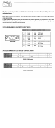
1 GND Normal 2 Digital Opi | 5 = AGC Alarm Lo OV = Normal 3 Digital Out | 5 = AGC Alarm 8 Analog Output FWD Power 9 Analog Output FWD Power AGC DBS Racket 2.5 PREVENTIVE MAINTENANCE To ensure maximum performance and minimum repair trouble, we strongly recommend you to follow the below stated headlines for preventive maintenance: 1. check antenna installation and ground connection at regular intervals; 2.
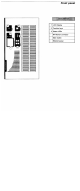
Front panel LCD Display Function keys Status LED RF Monitor connector Main switch R8232 Socket oo kinsfolk] a
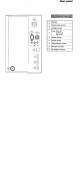
Rear panel Le 1 | Breaker ole = 2 | Rawer supply socket 3 | Auxiliary socket Fuse: Drive 5A 4 Control 1A Fan 3.