
Installation Guide

NICOR, Inc. 2200 Midtown Place NE, Albuquerque, NM 87107 P: 800.821.6283 F: 800.892.8393 www.nicorlighting.com July 26, 2021 10:46 AM
ECL3 Slim LED Combo Exit Sign & Emergency Light
INSTALLATION INSTRUCTIONS
Model: ECL310UNVWHG2SD, ECL310UNVWHG2RSD,
ECL310UNVWHR2SD, ECL310UNVWHR2RSD
What’s In The Box
One (1) ECL3 One (1) Mounting Kit
Tools Needed
A Phillips screwdriver will be needed to install the ECL3.
A drill is needed to remove the knockouts if back
mounting.
Make sure all power is turned o before beginning installation
READ AND FOLLOW ALL SAFETY INSTRUCTIONS.
• Review the diagrams thoroughly before beginning.
• All electrical connections must be in accordance with local codes, ordinances, and the National Electric code.
• Disconnect power at fuse or circuit breaker before installing or servicing.
• Do not use outdoors.
• Do not let power supply cords touch hot surfaces.
• Do not mount near gas or electric heaters.
• Equipment should be mounted in location and at heights where it will not readily be subject to tampering by unauthorized personnel.
• The use of accessory equipment not recommended by the manufacturer may cause an unsafe condition.
• Do not use this equipment for other than intended use.
• All servicing should be performed by qualied personnel only.
• Allow battery to charge for 24 hours before rst use.
• Max mounting height 17ft
SAVE THESE INSTRUCTIONS
Preparation
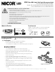
• Carefully unpack the exit sign from its packaging.
• Inspect product for defects due to shipping.
•
Use screwdriver to carefully remove the front faceplate (See Figure 1)
Mounting and Wiring
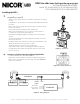
Wall Mount (See Figure 2)
•
Use screwdriver to carefully remove the front faceplate.
•
Remove the knock out hole on the center of back plate. Then
remove the oblong knock outs on the back plate that correspond to
junction box holes to be used.
•
Remove the side hole plugs from the housing and snap the lamp
heads onto the unit.
•
Connect the lamp head wiring to the circuit board.
•
Route supply wiring through the center hole and into the housing.
•
Install the xture on the junction box using the (2) included screws
(#8-32)
•
Connect the wiring per the wiring diagram and push excess wire
into the junction box.
•
Attach the battery connector to the circuit board.
•
Snap out the desired chevron marking(s) from the front faceplate,
reinstall the faceplate and adjust the direction of the lamp heads as
needed.
1
Installing the ECL3
Figure 2 - Back Mount
Figure 1 - Faceplate Removal
Flexible Conduit Only