
Installation Guide

NICOR, Inc. 2200 Midtown Place NE, Albuquerque, NM 87107 P: 800.821.6283 F: 800.892.8393 www.nicorlighting.com July 26, 2021 10:46 AM
ECL3 Slim LED Combo Exit Sign & Emergency Light
INSTALLATION INSTRUCTIONS
Model: ECL310UNVWHG2SD, ECL310UNVWHG2RSD,
ECL310UNVWHR2SD, ECL310UNVWHR2RSD
Mounting and Wiring
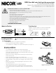
Ceiling Mount (See Figure 3)
•
Attach crossbar to junction box so that the short blade is touching
the box.
•
If double face is desired, replace back plate with additional faceplate
provided.
•
Remove the side hole plugs from the housing and snap the lamp
heads onto the unit.
•
Connect the lamp head wiring to the circuit board.
•
Remove the mounting hole cover on the top of the unit and
assemble the canopy to the unit (Figure 4)
•
Route xture wiring through the mounting hole and out of the
canopy.
•
Connect the wiring per the wiring diagram and push excess wire
into the junction box.
•
Install the xture on the junction box using the (2) included screws
(#8-32) and fasten the canopy to the crossbar.
•
Attach the battery connector to the circuit board.
•
Snap out the desired chevron marking(s) from the faceplate(s),
reinstall the front faceplate and adjust the direction of the lamp
heads as needed.
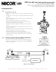
Connection of remote emergency lights (if applicable)
• Use Pink and Black wires for remote xture(s).
• Route wires outside of xture separately or with AC supply wires.
• Makes sure to keep all wires out of the way of the EXIT LEGEND so
there are no shadows.
Figure 3 - Top Mount
Installing the ECL3
2
3
Figure 5 - Wiring Diagram
Ready
Light
Test
Black (120Vac)
Battery
2.4 VDC 1Ah
Battery
1.2 VDC 1Ah
Red(+) Black (-) Red(+ ) Black (-)
Pink (+)
Black (-)
Orange (277 Vac)
White (Comm)
LED BOARD
LED
Pink (+)
Black (-)
LED
LED DRIVER
Figure 4 - Canopy Attachment