
Installation Guide

NICOR, Inc. 2200 Midtown Place NE, Albuquerque, NM 87107 P: 800.821.6283 F: 800.892.8393 www.nicorlighting.com December 10, 2019 11:30 AM
ECL5 LED Combo Exit Sign & Emergency Light
INSTALLATION INSTRUCTIONS
Model: ECL51UNVWHR2, ECL51UNVWHG2
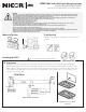
What’s In The Box
One (1) ECL5 One (1) Mounting Kit
WARNING
- Risk of re or electric shock. LED installation requires knowledge of luminaires electrical systems. Review the diagrams thoroughly
before beginning. All electrical connections must be in accordance with local codes, ordinances, and the National Electric Code. If
not qualied, do not attempt installation. Contact a qualied licensed electrician.
- Before installation, disconnect the power by turning o the circuit breaker or by removing the appropriate fuse at the fuse box.
Using the light switch to turn power o is not sucient to prevent electrical shock.
- May be used outdoors under cover. (-15°C - 40°C)
- Do not let power supply cords touch hot surfaces.
- Do not mount near gas or electric heaters.
- Use caution when servicing batteries, all servicing should be completed by qualied personnel. Replace every 8 to 10 years
according to ambient. Test regularly in accordance with local codes.
- To prevent wiring damage or abrasion, do not expose wiring to edges of sheet metal or other sharp objects.
- Do not use this equipment for other than its intended use.
- The use of accessory equipment not recommended by the manufacturer may cause an unsafe condition.
- Equipment should be mounted in locations and at heights where it will not be subjected to tampering by unauthorized personnel.
- Only use UL Listed, Suitable for Wet Location conduit parts. Use exible conduit ONLY.
- Allow batteries to charge for 24 hours before rst use.
Tools Needed
A Phillips screwdriver and a drill will be needed to install
the ECL5.
Make sure all power is turned o before beginning installation
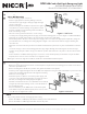
Preparation
Carefully unpack the exit light from its packaging. Inspect product for defects due to shipping. Become familiar
with the wiring diagram below before beginning installation. Take the faceplate o of the xture, remove the plastic
diuser. Remove the appropriate chevron arrow knockout, gently using your ngers or a small tool, then replace the
plastic diuser. If using double face option, remove the appropriate chevron arrow of the second faceplate. Set the
faceplate(s) and screws aside.
1
Installing the ECL5
Figure 1 - Wiring Diagram
Figure 2 - Chevron Arrow
Removal