
Installation Guide

NICOR, Inc. 2200 Midtown Place NE, Albuquerque, NM 87107 P: 800.821.6283 F: 800.892.8393 www.nicorlighting.com December 10, 2019 11:30 AM
ECL5 LED Combo Exit Sign & Emergency Light
INSTALLATION INSTRUCTIONS
Model: ECL51UNVWHR2, ECL51UNVWHG2
2.1
2
2.1
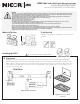
Mounting Instructions
Surface Wall Mounting
• If back mounting, skip to section 2.2.
• Remove appropriate knockout by drilling a 3/4” hole.
• Thread nut onto pipe nipple. Slide pipe nipple through
canopy center hole.
• Remove backing from self adhesive junction box gasket
and adhere to back of mounting canopy. Remove back-
ing from self adhesive pipe thread gasket and adhere to
front of mounting canopy.
• Place the screws provided in the holes on the canopy.
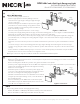
• Feed the power supply through knockout, pipe, and metal mounting plate, as seen in “Figure 3 - Wall Mount.” Direct
input wires along walls of the xture to protect the wires and prevent shadowing.
• Ensure that power is o, then connect the power supply, 120 or 277 VAC, to the appropriate input wires, using the
provided wire nuts, according to the wiring diagram in Figure 1. The unused wire must be capped o using the
extra wire nut.
• Push wire connections into the junction box. Mount metal bracket to junction box (j-box and hardware not includ-
ed).
• Secure the canopy to the steel mounting plate. Place pipe nipple through the mounting hole of the housing to
lock the canopy into place. Once canopy is locked into position there will not be any side-to-side movement of the
canopy.
• Connect batteries to LED board using snap in connectors. Secure the faceplate(s) to the xture: snap in the white
faceplate, then screw on clear cover. Do not over tighten screws.
NOTE: Figure 3 shown as single face install, for double face: install additional EXIT faceplate.
2.2
Back Mounting
• Drill or knock out appropriate knockouts on the backplate to t junction box mounting points and the center knock-
out for the input wire leads.
• Remove backing from self adhesive junction box gasket and adhere to back plate.
• Feed the power supply through the knockout. Direct the input wires along the walls of the xture to protect the wires
and prevent shadowing. Run the wires through the mounting
bracket as seen in Figure 4.
• Ensure that power is o, then connect the power supply, 120
or 277 Vac, to the appropriate input wires, using the provided
wire nuts, according to the wiring diagram in Figure 1.
• Mount the metal bracket to the J-box (hardware not included).
• Using the provided (2) mounting screws, secure the xture to
the mounting bracket.
• Connect the battery to the LED board. Secure the faceplate
to the xture: snap in the white faceplate, then screw on clear
cover. Do not over tighten the screws.
Figure 3 - Wall Mount
Figure 4 - Back Mount
NOTE
Battery Testing: Allow 24 hours of charging before testing.
• Push In TEST Button - LED display will switch to battery power and remain lit
• Release TEST Button - LED display will switch back to AC power
Large
Gasket
Small
Gasket
Small
Gasket
Large
Gasket