
Full Product Manual


10
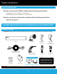
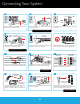
Connecting Your System
8
Connect the red female power leads of the video / power
cables to the male power splitter ends.
POWER SPLITTER
CONNECTORS
POWER CABLE
CONNECTORS
1
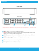
Plug one end of the included HDMI cable into the
HDMI port on the back of the DVR.
HDMI
9
Connect the power splitter to the camera power
adapter and plug the adapter into a surge
protector or Uninterruptible Power Supply (UPS).
CAMERA POWER
ADAPTER
POWER
SPLITTER
SURGE PROTECTOR
(NOT INCLUDED)
Plug the other end of the Ethernet cable into a port
on the back of your router or modem.
ETHERNET
ROUTER
(NOT INCLUDED)
5
RESET
LAN1 LAN2 LAN3 LAN4WAN
2
Plug the other end of the HDMI cable into the back
of your TV or Monitor.
HDMI
NOTE: To view cameras, TV or Monitor must be
tuned to the same input the HDMI is plugged into.
STOP: BEFORE installing, connect and test each
camera locally to confirm they function properly.
P
WR
HD
D
6
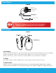
Connect the end of the camera’s cable to the end
of a video / power cable labeled TO CAMERA ONLY.
VIDEO / POWER CABLEFROM CAMERA
To
CA
M
ER
A
To
C
A
6
Plug the USB mouse into the USB port on the back
of the DVR.
3
USB
Plug one end of the included Ethernet cable into
the LAN port on the back of the DVR.
4
ETHERNET
NOTE: Night Owl recommends connecting to the
Internet for the best user experience.
SURGE PROTECTOR
(NOT INCLUDED)
Plug the DVR power adapter into a surge
protector or Uninterruptible Power Supply (UPS).
Some systems beep upon booting up.
NOTE: Make sure the UPS or
surge protector is switched ON.
11
7
Connect the video / power cable labeled TO
DVR ONLY to an open video input on the DVR.
NOTE: Make sure you twist
and lock BNC connectors.
10
Connect the DVR power adapter to the Power Input
on the rear of the DVR.
POWER